Responsible: Adrian Iovan, Carlota Canalias, Anders Liljeborg
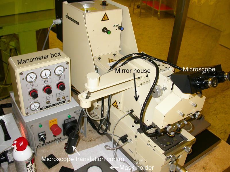
Service: replacement of air-cylinder for mirror house movement.
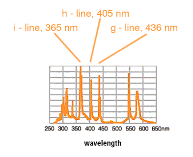
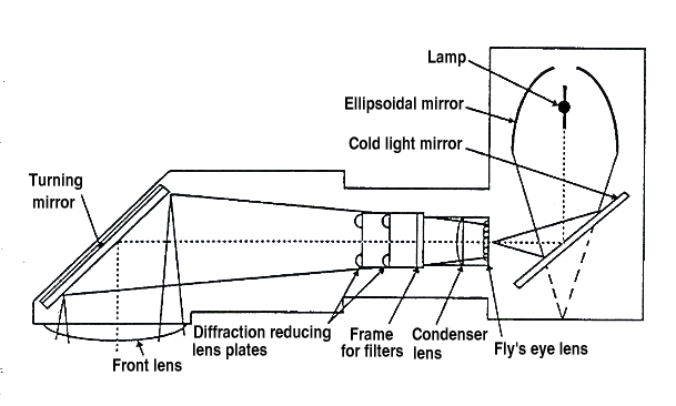
Below is a typical mercury spectrum. In the mask aligner the i- h- and g-lines can be used. Currently only the g-line is used for exposure, this is optimum for S-1800 series photo-resist. To use the shorter wavelengths would give higher resolution but require the optics to be changed in the system.
| Before | NOW |
|---|---|
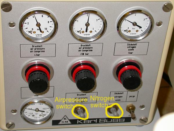
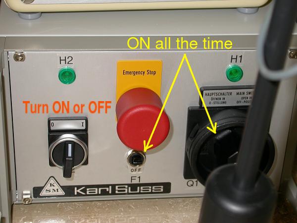
| Turn on/off complete system, also nitrogen in service corridor | ONLY turn on/off N2 and air-switches on the maskaligner control unit |
| No vacuum -> no possibility of different exposure modes | Vacuum is available. Possibility to select exp. modes |
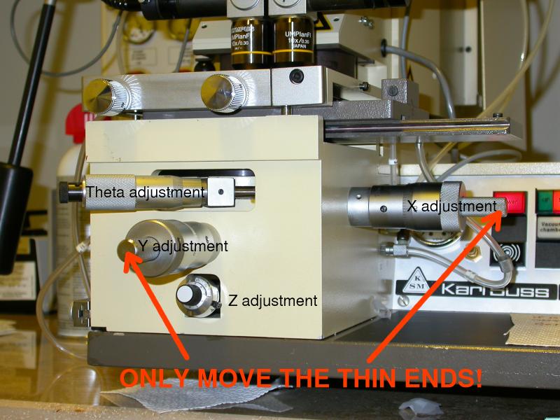
| Height adjustment while in contact | NEVER height adjustment in contact |
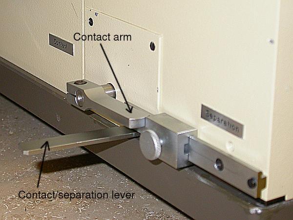
| The separation lever was never used | The separation lever MUST be used |
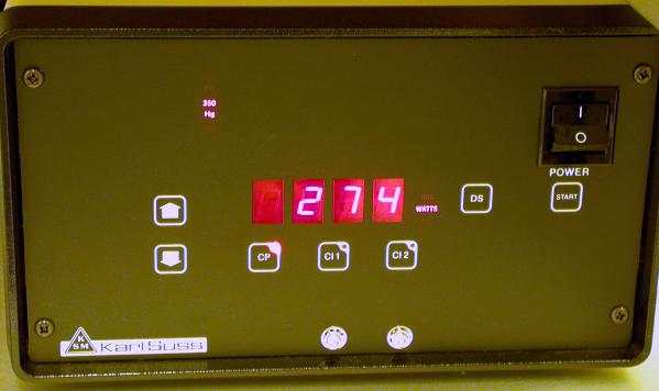
| Exposures in constant power mode | Exposures in constant intensity mode, higher repeatability |
| Mode | How does it work? | Resolution | Comments |
|---|---|---|---|
| Vacuum Contact (HP) | Vacuum is made between the mask and
the wafer prior to exposure | ≅0.8 µm pitch | RISK OF BREAKING THE MASK |
| Standard (ST) Hard contact mode | During exposure the vacuum holding the substrate to the chuck is switched off and positive nitrogen pressure is used to press the substrate against the mask | ≅1.5 µm pitch | RISK OF BREAKING THE MASK |
| Soft contact mode | The substrate is held to the mask only by mechanical pressure of chuck throughout the exposure. The vacuum holding the substrate to the chuck remains on | ≅2 µm pitch | SAFE |
| Proximity contact | Exposures are made with a small gap between the mask and substrate. The gap is determined by height adjustment | Depends on separation | SAFE. It has to be adjusted manually. |
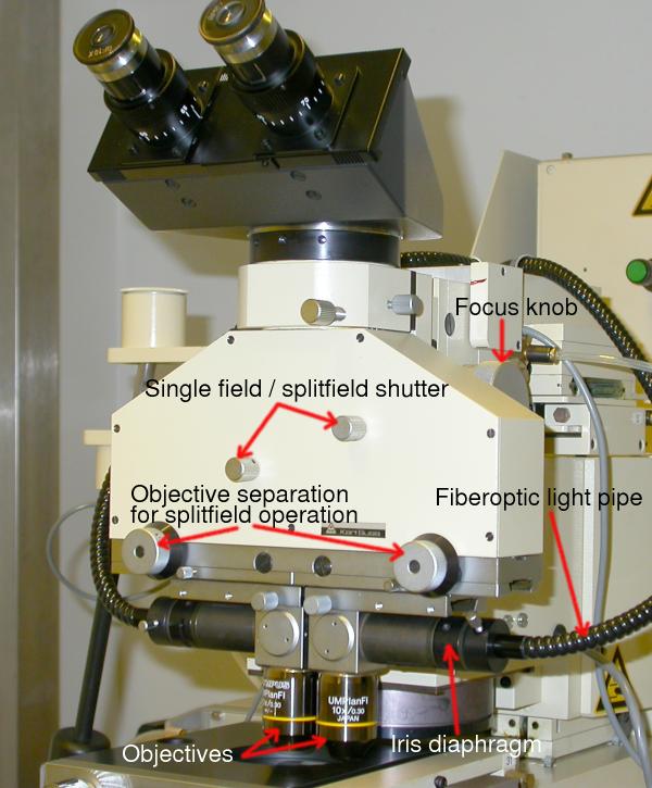
| Splitfield | Left objective | Right objective |
|---|---|---|
| Half field of view from left obj.,
half from right obj. | Image only from left obj. | Image only from right obj. |
| Left shutter fully clockwise
right shutter fully anti-clockwise | Left shutter halfway
right shutter fully anti-clockwise | Left shutter fully clockwise
right shutter halfway |