Fluorescence microscope & cooled CCD camera
Responsible:
Anders
Liljeborg
Short user guide
Overview of the fluorescence microscope with cooled CCD camera
NEW!
Scale-bars for the different objectives
and magnifications
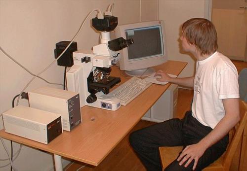
This is the fluorescence microscope equipped with a cooled CCD camera.
From left to right are shown:
- Power supply for CCD camera
- Power supply for mercury lamp
- Microscope with CCD camera on top
- Computer screen
- Operator
The microscope is equipped with four objectives:
(wd = working distance,
NA = Numerical Aperture, NCG = No Cover Glass)
- 10x/0.25 NA air, wd=12.5 mm
- 50x/0.75 NA air, wd=0.4 mm
- 100x/0.95 NA air, wd=0.32 mm
- 100x/1.4 NA oil, wd=0.17 mm, NCG
Warning!
The Mercury lamp must burn for at least one hour when turned on.
Typically it should not be turned off for a lunch-break, it should be
left running.
This is because certain vapors in the lamp can form stable residues
on the inside of the lamp-glass, thus reducing the light intensity
and the life span of the lamp.
|
The 100x/1.4 NA oil-immersion objective should always be used with a drop
of immersion oil on the specimen. Wipe the objective with lens-cleaning
paper after use.
|

|
The CCD camera is monochrome and has an
optical resolution of 1600 × 1200 7.4 µm square pixels. Image area
is 11.8 × 8.9 mm.
|
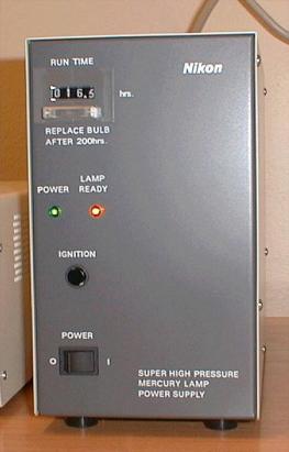
The power supply for the mercury vapor lamp.
- At the top is the hour counter for the burn-time of the lamp.
- Power LED and mercury lamp ready indicator
- Ignition button
- Mains power switch
When turning on the lamp:
- first turn on the power switch
- then press and hold down the ignition button until the
orange "Lamp Ready"
is lit and the run time counter has advanced one tenth-hour step.
Warning!
The Mercury lamp must burn for at least one hour when turned on.
Typically it should not be turned off for a lunch-break, it should be
left running.
This is because certain vapors in the lamp can form stable residues
on the inside of the lamp-glass, thus reducing the light intensity
and the life span of the lamp.
When turning off the mercury lamp; turn off the power switch.
Note: there is no way to vary the intensity of the mercury
lamp electrically, this must be done with
grey-filters.
|
|
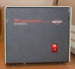
The power supply for the CCD camera. A simple On/Off switch,
just turn it on at the beginning of the session, turn it off when
you are finished.
|
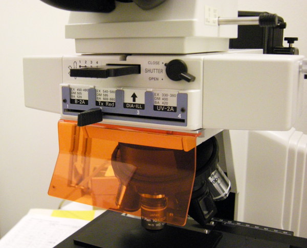
This is the center of the microscope, the epi-illumination fluorescence
unit.
The slider with four positions is controlling which filter block is
in the light path, thus selecting which type of fluorescence to detect.
- Position #1 labelled B-2A is for fluorescence viewing/detection.
This is for fluorophores using blue excitation light and
emitting green fluorescence, specifically FITC.
A bandpass filter is letting through excitation light in the wavelength
range of 450 - 490 nm, and an emission filter is letting through light
with wavelengths longer than 520 nm. In between these two filters
there is a dichroic beam-splitter with a split wavelength of 505 nm.
-
Position #2 labelled Tx Red (after fluorophore Texas Red) has an
excitaion range of 540 - 580 nm (green excitation) and fluorescence
range of 600 - 660 nm with dichroic beamsplitter at 595 nm.
-
Position #3 labelled "DIA-ILL" is for reflected light.
Most of the spectrum from the mercury lamp is used both for illumination and
for viewing/detection. A 50/50 beam-splitter is installed in this filter block.
Here the grey filters can be useful for reducing
the light intensity.
-
Rightmost position (#4) is labelled UV-2A has an ultraviolet
excitation range of 330 - 380 nm and fluorescence range of > 420
nm. The dichroic beamsplitter is at 400 nm.
Assisting here is a bandpass filter located in the black holder
directly above the slider. The filter is labelled "XF 3080
510AF23 466 0130". This means 510 nm center wavelength and 23 nm
full-width-half-maximum. It is a narrow band filter to help reduce
sample auto-fluorescence. Can also be helpful for discrimination from
red emitting fluorophores such as mRFP. Should be used together with
position #1, possible fluorophores eGFP, Fluorescein (FITC), Alexa
Fluor 488, Cy2.

At the top right corner there is a shutter to block the excitation light
from the specimen when not looking at it. This is a very useful item
since the specimen can easily be bleached by the rather powerful mercury
lamp.
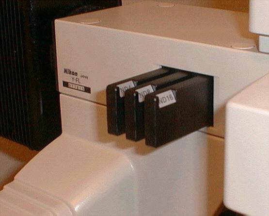
The grey filters (neutral density filters) to vary the intensity
of the illumination/excitation light.
There are three grey filters used to vary the intensity of the
illumination/excitation light. These are labelled:
- ND4 reduces intensity with a factor of 4 (25%)
- ND8 reduces intensity with a factor of 8 (12.5%)
- ND16 reduces intensity with a factor of 16 (6.25%)
The filters are used by pushing them into the light path in any combination.
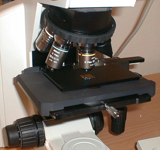
The objectives in their revolver, the specimen stage and the
focusing knobs.
Here is the stage where a Si-chip layered with gold is studied.
Note the little bluish spot where the excitation light illuminates the
chip.
At the lower left is the focusing knob:
- The outermost (leftmost) knob is for fine focus. The
rotary scale is in microns.
- The wide center knob is the coarse focus. When using it be very
careful not to push the specimen into the objective. This might damage
both your specimen and the objective!
- The innermost ring is the adjustment for friction of the coarse focus.
At the lower right can be seen the knobs for moving the stage laterally.
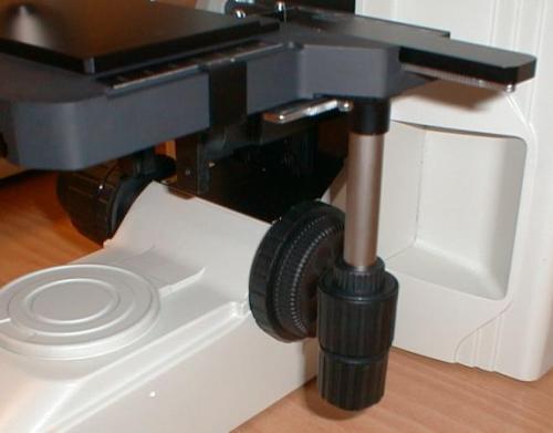
The stage and focus knobs seen from the left side.
Here knobs for moving the stage are more clearly seen.
Behind them is a dual knob. The outer part is a fine focus knob so
fine focus can be adjusted with either hand.
The inner ring is a locking ring which stops the coarse focus from
moving the stage above a certain level. This can be very useful to
protect oneself from pushing the specimen into the objective:
- Loosen the locking ring
- With the coarse focus knob find the highest safe position for
focusing without touching the objective
- Tighten the locking ring
Now the stage cannot be moved upwards more than for focusing, it stops
before the specimen touches the objective. To release the lock just loosen
the locking ring.
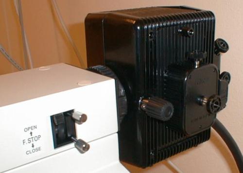
Housing of the mercury lamp.
It can become quite hot, so do not
touch it. There are several adjustment screws for aligning the lamp when it
has been replaced. These screws should not be touched without knowledge.
To the left is the control for the field stop. It can be used to limit
the circular field that is illuminated on the specimen. The black knob
adjusts the size (diameter) of the field, the two blank metal knobs
adjust the centering of the field inside the field-of-view.
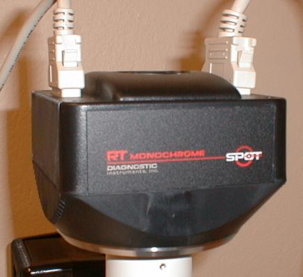
At the top of the microscope the CCD camera is attached.
The CCD camera is a SPOT RT Monochrome manufactured by Diagnostics Instrument.
It has a CCD made by Kodak, KAI - 2000, with protective cover glass removed.
Optical resolution is 1600 × 1200 7.4 µm square pixels. Image area
is 11.8 × 8.9 mm.
Bit depth: 8 or 12 bits, binning: 2×2, 3×3, 4×4.
CCD cooling: 37° differential from room temperature (-12°C at 25°C
room temperature). Stability: ± 1°C per 8 hour period.
Dark current: 0.15 electrons per pixel per second (e/p/s) at -12°C (typical).
Full scale charge: 35,000 e¯.
Signal to Noise Ratio: 46 dB, limited by photon quantum noise (Poisson
statistics).
Dynamic range: 60 dB.
Anti-blooming factor: 300 times (nominal), 100 times (minimum).
Quantum efficiency see diagram:
There is also a camera window affecting the spectral response
of the camera. It is made of UBK7 glass with 320 - 900 nm anti reflective
coating. See transmission diagram:
Anders Liljeborg
Albanovs Nanolab, KTH.