Dimension AFM
Erik Tholén, 2012-03-01
Step-by-step instructions
The purpose of these instructions is to help a beginner to remember
everything that has to be done in order to scan an image. More
experienced users are expected to chose other settings that suit them
better.
Start the system
- Turn on the computer and log in.
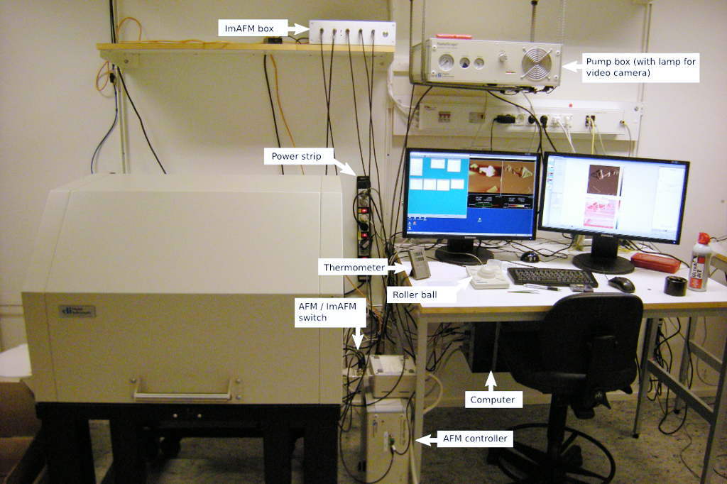
- Make sure the computer button on the "power strip" is on.
- Start the computer. In the boot menu, choose winXP.
- Log in, the user name and password are on a label on the edge of the screen.
- Turn on the AFM system (computer must be logged in first).
- Make sure the AFM button on the "power strip" is on.
-
Make sure "AFM controller" is on. Check the lamp on the front panel.
Otherwise the power button is on the back side of the "AFM controller".
- Make sure the 'pump box' is on. Check the lamps on the
front panel. Otherwise the power button is on the back side of the
'Pump box'. (The right side of the back side)
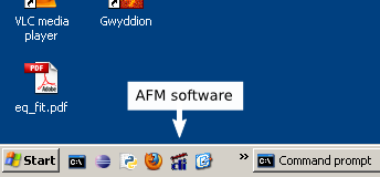
- Start the
AFM software on the computer. Click the microscope button in the
toolbar of the AFM software to connect to the microscope.
- Choose mode of operation.
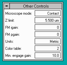 With the Dimension AFM we usually do "Contact mode", "Tapping mode" or "ImAFM mode".
- For "Contact mode", set the "AFM/ImAFM" switch to "AFM" and the "Microscope mode" in the AFM software to "Contact".
- For "Tapping mode", set the "AFM/ImAFM" switch to "AFM" and the "Microscope mode" in the AFM software to "Tapping".
- For "ImAFM mode", set the "AFM/ImAFM" switch to "ImAFM" and the "Microscope mode" in the AFM software to "Contact". Make sure that the ImAFM box is turned on.
Prepare for scanning

- Move the stage all to way out. (Click "Stage" -> "Load new sample" or see "Moving the stage below".)
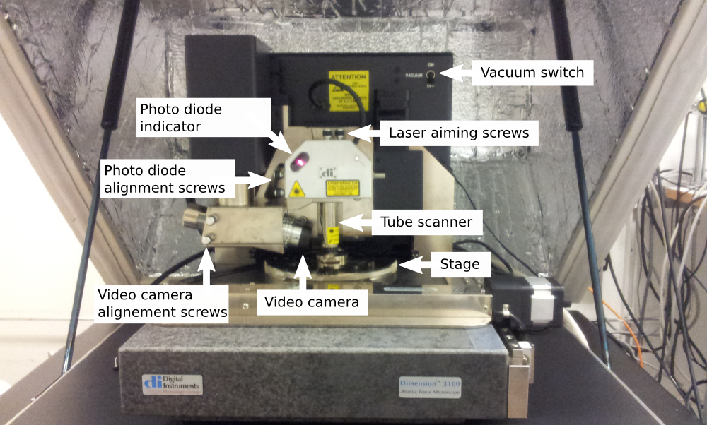
- Mount a cantilever in the cantilever holder and mount the cantilever holder on the tube scanner.
- Align
the laser spot on the end of the cantilever with the "Laser aiming
screws". The "Sum" in the AFM software should be 4-6 V (see image on
the right).
- Use the "Mirror adjustment screws" to center the laser spot in the "Laser reflection window".
- Use
the "Mirror adjustment screws" to center the laser spot in the
"Detector" in the AFM software, see image on the right. Set the "Horiz
defl" to 0 V (± 0.1 V).
- For Contact mode, the "Vert defl" should be -2 V (± 0.1 V). I.e. the laser spot should not be in the center.
- For Tapping mode the "Vert defl" indicator is replace by and "RMS" indicator (Not interesting right now).
- For ImAFM mode the "Vert defl" should be 0 V (± 0.1 V).
- Put
your sample on the stage. If your sample is very light weight you must
secure it from moving around while scanning. If your sample is very
thin you must raise it up a little bit, you can use for example a
microscope slide or a magnetic puck.
- Move the stage so that the spot from the video camera lamp is on the sample.
- In
the menu bar, select "Stage" -> "Focus surface" (if you did not do
that in the previous point). Click the "Zoom out" button if possible;
it is always easier to find the focus when zoomed out. Choose if you
want to focus on the surface (for normal surfaces) or on the tip
reflection (for smooth and clean surfaces without features). Press the
foucs button on the roller ball and roll the ball up or down to move
the "tube scanner" up or down. Always watch the "tube scanner" to make
sure you do not crash in to the sample. When you can barely see a
separation between the cantilever and the sample it is time to watch
the video window on the computer screen to fine tune the focus. To fine
tune the focus even more you can zoom in by pressing the zoom button on
the roller ball and roll down. When you have good focus, press "OK".
- In
the menu bar, select "Stage" -> "Locate tip". Use the "video camera
alignment screws" to locate the cantilever under the cross hair. Use
the roller ball to focus os the tip of the cantilever.
- In the menu bar, select "Stage" -> "Focus surface" again and verify that you still have a good focus here.
- If you are going to use "Tapping mode", press the tuning fork button
 in the AFM software. Make sure that the resonance frequency is in the
range given by the "Start frequency" and "End frequendy" fields. Then
press "Auto tune". Sanity checks:
in the AFM software. Make sure that the resonance frequency is in the
range given by the "Start frequency" and "End frequendy" fields. Then
press "Auto tune". Sanity checks:
- You should see a resonance curve in the plot window.
- The drive amplitude is normally 50-500 mV.
- The RMS amplitude is normally ~2 V.
When to auto tune is finished, press back to image mode.
- Set up scan controls in the AFM software.
For ImAFM mode: read off the scan rate in the ImAFM software and type the scan rate in the "Scan Controls" window.
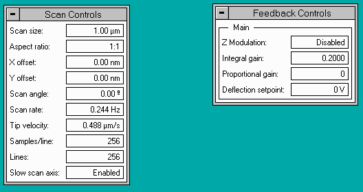
- Set up the "Feedback Controls" in the AFM software.
- In Contact mode: Integral gain = 2.0, Propotional gain = 3.0, Setpoint = 0 V
- In Tapping mode: Integral gain = 0.5, Propotional gain = 0.7. Don't change setpoint, it is automatic.
- In ImAFM mode: Integral gain = 0.2, Propotional gain = 0.0, Setpoint = 0 V
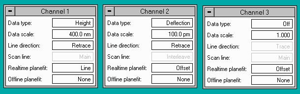
- Set up the channels. Channel 1 Data type should be Height.
- For Contact mode: set Channel 2 Data type: Deflection and Channel 3 Data type: Off
- For ImAFM mode: set Channel 2 Data type: Deflection and Channel 3 Data type: Off
- For Tapping mode: set Channel 2 Data type: Amplitude and Channel 3 Data type: Phase
Make sure that the line direction is the same for all channels.
- For ImAFM mode set up the ImAFM software.
- Press the engage button
 to start scanning. The AFM will no slowly move the tip towards the
surface. Normally it finds the surface and starts scanning when the
piezo is at ~80 µm.
to start scanning. The AFM will no slowly move the tip towards the
surface. Normally it finds the surface and starts scanning when the
piezo is at ~80 µm.
Adjusting the scanning.
- For ImAFM mode click the measure free button in the ImAFM sotware.
- Click the scope mode button
 to open the scope mode.
- Change the "Data scale" in every channel to make the curves fit in the window.
- The goal now is to make the trace and retrace curves follow each other without having feedback oscillations.
- For Tapping mode
it is often a good start to lower the setpoint. Click on the setpoint
value and the hit the left arrow on the keyboard. Repeat if necessary.
- Change
the integral controls so that the trace and retrace curves follow each
other. Increasing the Integral gain will make the curves follow each
other better, but too much Integral gain will cause feedback
oscillations.
- The Proportional gain often has no significant effect.
- For ImAFM mode click the measure free button in the ImAFM sotware again.
- Click the imaging mode button
 to return to the images.
Saving data
- In the AFM software, go to the top menu bar and select
"Capture" -> "Capture filename". Type a filename without using space
bar, _underscore_ is ok. Press ok.
- Press the camera button
 in the tool bar and watch the Capture in the status bar.
- Off means it will not save any data, press the camera to change.
- On
means it will save the current image when it is complete. It will then
switch to off so that the next image will not be saved unless you press
the camera again.
- Next indicates that you have
changed a parameter and therefore want to wait until the next image is
complete before saving (i.e. it will not save the current image). Click
the camera to save the current image.
- Force indicates that you have changed a parameter but you still want to save the current image when it is complete.
- Note
the if Capture is "On" and you change a parameter, it will
automatically change to "next". Then you must remember to press the
camera again if you want to save the current image.
- Note
that if you are in scope mode instead of imaging mode, only the scope
trance will be saved, not the image. Click the imaging mode button to return to imaging mode.
- If you want to save every scan automatically you can choose "Capture movie".
Moving the stage
To move the stage: Go to the menu bar of the AFM software and select
"Stage" -> "Focus surface". You can then use the roller ball to move
the stage around. Note that there is a considerable lag time between
rolling the ball and the movement of the stage. It is therefore
recomended to wait for every move to complete before starting a new
movement. If you need to move a long distance is is practical you press
the "Lock" button on the roller ball before rolling. The stage will the
continue to move in the same direction until you release the lock
button.
When you need to change cantilever or sample you can make the stage
move all the way out automatically: Go to the menu bar of the AFM
software and select "Stage" -> "Load new sample". Click "OK" in the
dialog box. The stage will the move all the way out so that you can
change cantilver or sample. When you are done you can again select
"Stage" -> "Load new sample" and the stage will move back to the
same place again. If the AFM software is started (or restarted) with
the stage moved it does not remember the position to move it back to.
You must therefore move the stage in again manually, follow the
paragraph above.
Secure the sample from moving around
If your sample is very light weight you must secure it from moving around while scanning. There are two alternatives:
- Put the sample on the hole in the center of the stage. Turn
on the "Vaccum switch". You can feel if the vaccum is "leak tight" by
moving the sample a little bit. If it does not "stick" you must use
method 2 below. Don't forget to switch off the vaccum before removing
the sample.
- Use double sided "sticky pads" to tape your
sample on a small magnetic puck or a microscope slide. These accesories
are found in the cabinet by the wall to the right of the AFM.
Shut down
- Press the disengage button
 in the tool bar.
- In the menu bar of the AFM software, press "Stage" -> "Load new sample" -> "ok".
- Remove your sample.
- If
the cantilever tip is ok you can remove it and save it or leave it for
the next user. If the tip is bad you should remove it and throw it away.
- Press the
 -button
in the tool bar and double click once on every new image you took. This
will make the images readable by other software such as Gwyddion or the
ImAFM batch processor.
-button
in the tool bar and double click once on every new image you took. This
will make the images readable by other software such as Gwyddion or the
ImAFM batch processor.
- If you a copy of the images you took you can find them in C:\capture
- To open the image files we recommend Gwyddion.
Trouble shooting
ImAFM software setup
Note: To run ImAFM mode the "AFM/ImAFM switch" should be in the ImAFM position and the "Microscapoe Mode" in the AFM software should be set to "Contact"
ImAFM software setup
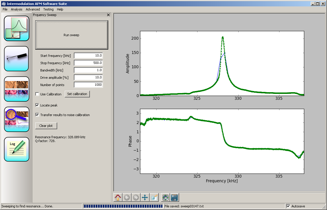
- Start the ImAFM software suite.
- Press the "Run sweep" button. The software will now try to find the resonance frequency. The result should look like this:
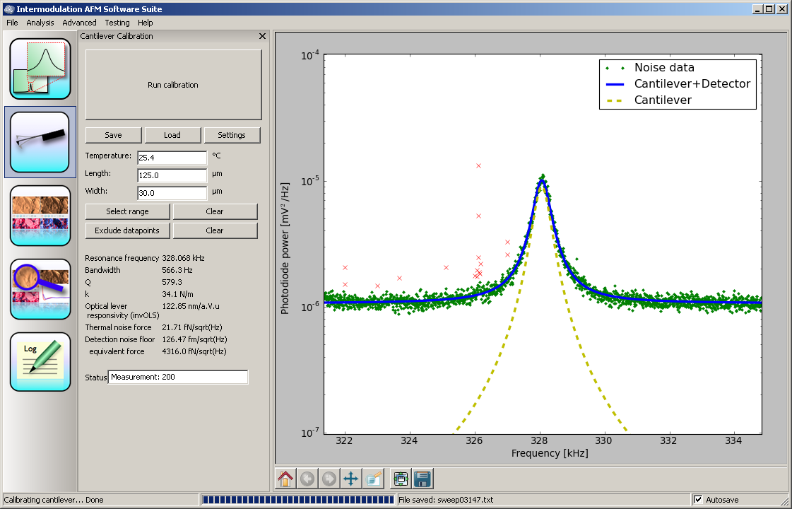
- Press the Calibrate cantilever icon.

- Press
the "Run calibration" button. Wait for the software to complete the
data acquisition, watch the progress bar at the bottom of the window.
- Click
the "Select range" button and click-and-drag to select a region around
the resonance that also includes some of the flat parts of the spectrum.
- Click the "Exclude datapoints" button and click-and-drag squares around bad data points.
- The result should look like this:
- Press the scanning icon.

- Press the Setup button
- Press the "Start" button
- Read off the scanrate in the ImAFM software and type the scan rate into the AFM software.
- Now the ImAFM software is ready for engage. (Engage with the -button in the AFM software)
While scanning with ImAFM
- Press the "Remeasure free" button to recalibrate the free oscillations.
- To get a force curve: Select the cross in the toolbar and click in the image.
Turn-off policy
- When the computer turns on, it sends some funny commands on
the serial port that makes the pump box behave funny. Therefore it is
good to have the pump box off while turning on the computer.
- Electronincs may
live longer if it is not turned on and off too much. Therefore it is
good to leave the electronics turned on if you know that someone will
be using the system within one week.
- But the pumps and the
laser will live longer if they are turned off when not used. Therefore,
turn off the laser by closing the AFM software and turn off the pump
box with the switch on the back side (right hand).
Erik Tholén,
Anders Liljeborg
Nanostructure Physics, KTH.