Open Loop C-AFM Imaging
| |
- Set the parameters listed in Table 1 in the C-AFM panel.
|
| Parameter |
Value |
| DC Sample Bias
|
0 V |
| Current sens |
1 nA/V |
| DC Test Bias
|
0 V |
Table 1: Initial settings of C-AFM panel parameters
NOTE: Conductive AFM is a Contact Mode technique. For the initial settings of the Scan parameters and the Feedback parameters in Contact Mode, refer to your instruction manual. Typically, the
Feedback panel looks similar to what is shown in
Figure 1.
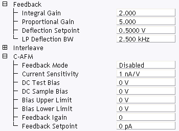
Figure 1: C-AFM control parameters in the Scan Parameter list
| |
- Set Feedback > Deflection Setpoint to no more than a few tenths of a volt above the engagement point. This will keep the contact force sufficiently low, thus not causing any damage to the tip or sample. This is especially important for metal coated tips or soft samples.
|

|
- Click Engage (shown) to start scanning.
|
NOTE: It will probably be necessary to make adjustments to a number of parameters (Integral Gain, Proportional Gain, Deflection Setpoint, etc.) before the image is optimized.
| |
- Set Channel 1 > Data Type to Height to view the topography and set Channel 2 > Data Type to C-AFM Current to view the current data.
- In the Channel 2 panel, set Real-time Plane Fit to None and the Offline Plane Fit to None.
|
NOTE: The
Center parameter in
Channel panels is useful for measuring small current variations in a sample with an overall larger background current. It offsets the centerline of the color scale by the amount entered. See
Figure 2.

Figure 2: Adjust the Center value in the C-AFM Current channel
| |
- To reduce tip and sample wear, decrease the contact forces between the tip and sample as much as possible:
- Observe the (Channel 1) Height Sensor trace.
- Highlight Feedback > Deflection Setpoint and click the left arrow key to reduce the force applied to the sample by lowering the setpoint incrementally. Repeat until the probe tip eventually lifts off the surface.
- Click the right arrow key as needed to obtain a focused image.
|
NOTE: Adjusting the Deflection Setpoint to a few tenths of a volt above the engagement point provides a low contact force.
| |
- Slowly increase the C-AFM > DC Sample Bias while watching the current signal. For many samples, the current increases rapidly beyond a threshold bias.
|
NOTE: Do not scan too fast. The sensor bandwidth is only 160 Hz. The slower a sample is scanned, the higher the spatial resolution the current sensor can detect. Adjust Scan > Scan Rate for image quality.
WARNING: Increase DC Sample Bias carefully: Metal coated tips can melt and the sample be damaged if the current density is too high.
WARNING: Electrostatic forces cause a strong attraction between the tip and most samples when a bias is applied. The electrostatic force does not result in additional deflection of the cantilever, but does induce more wear of the tip, and can damage soft samples, such as polymers. Reduce the Deflection Setpoint (see Step 6 to lower the tip/sample force. Alternatively, apply the bias first before engaging. However, the latter method works only for experiments with a well-defined, known bias. In most cases further adjustment of Deflection Setpoint is necessary.
| www.bruker.com
|
Bruker Corporation |
| www.brukerafmprobes.com
|
112 Robin Hill Rd. |
| nanoscaleworld.bruker-axs.com/nanoscaleworld/
|
Santa Barbara, CA 93117 |
| |
|
| |
Customer Support: (800) 873-9750 |
| |
Copyright 2010, 2011. All Rights Reserved. |
Open topic with navigation