 PeakForce TUNA Imaging
| |
- Set the parameters listed in Table 1 in the PF-TUNA panel.
|
| Parameter |
Value |
| DC Sample Bias
|
0 V |
| Current sens
|
20 pA/V |
| DC Test Bias
|
0 V |
Table 1: Initial settings of TUNA panel parameters
NOTE: PeakForce TUNA uses the
Bruker-proprietary PeakForce Tapping™ mode. For additional detail about this mode, refer to the
PeakForce QNM User Guide. Typically, the
Feedback panel looks similar to what is shown in
Figure 1.
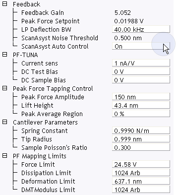
Figure 1: TUNA control parameters in the Scan Parameter list
Scan Panel
| |
- Set the Scan Size and Scan Angle.
|
Feedback Panel
| |
- Set ScanAsyst Auto Control to On.
|
Channels
| |
- Set the Channel 1 Data Type to Height Sensor (see Figure 2).
- Set the Channel 2 Data Type to Peak Force Error (see Figure 2).
- Set the Channel 3 Data Type to DMT Modulus (see Figure 2).
- Set the Channel 4 Data Type to LogDMT Modulus (see Figure 2).
- Set the Channel 5 Data Type to Adhesion (see Figure 2).
- Set the Channel 6 Data Type to Deformation (see Figure 2).
- Set the Channel 7 Data Type to TUNA Current (see Figure 2).
-
Set the Channel 8 Data Type to Peak Current or Contact Current (see Figure 2 ).
|


Figure 2: Suggested PeakForce TUNA Channel Settings
Engage

|
- Click Engage (shown) to start scanning.
|
Image the sample
| |
- If needed, right-click in the Force Monitor window and click UnDock. See Figure 3. You may Dock the undocked Force Monitor window by right-clicking in it and clicking Dock.
|
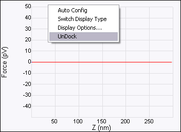
Figure 3: Undock the Force Monitor window
| |
- Select one plot to be Force vs. Time and the other to be Force vs. Z.
- Once scanning, the Force Monitor window, shown in Figure 4, should display a Force vs. Z plot and a “heartbeat” (Force vs. Time) plot.
|
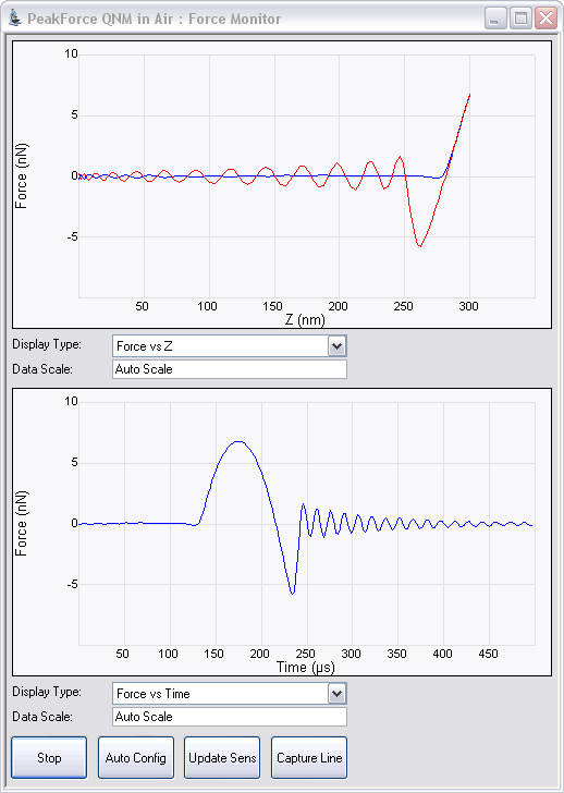
Figure 4: Force Monitor window
NOTE: The cantilever oscillation after it snaps off the sample surface, shown in
Figure 4, is normal. On occasion this oscillation will continue until the probe tip again contacts the sample surface. This oscillation will be heavily damped by this contact. Even if the oscillation is not fully damped, the remaining oscillation at the force peak will be small and will merely add a small amount of noise to the feedback.
| |
- The Height, Modulus, Adhesion, Current... channels will display the scanned image. See Figure 5.
|
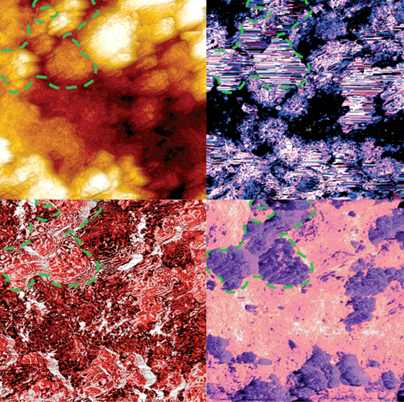
Figure 5: Simultaneous mapping of nanomechanical (Height: upper left, Modulus: upper right, Adhesion: lower left) and nanoelectrical (Current: lower right) properties on Lithium ion cathode (L333). Sample courtesy of Dr. Battaglia, LBL.
| |
- In the TUNA Current and Peak Current panel, set Real-time Plane Fit to None and the Offline Plane Fit to None.
|
NOTE: The
Center parameter in
Channel panels is useful for measuring small current variations in a sample with an overall larger background current. It offsets the centerline of the color scale by the amount entered. See
Figure 6.
Figure 6: Adjust the Center value in the TUNA Current channel
| |
- Slowly increase the TUNA > DC Sample Bias while watching the current signal. For many samples, the current increases rapidly beyond a threshold bias.
|
WARNING: Increase DC Sample Bias carefully: Metal coated tips can melt and the sample can be damaged if the current density is too high.
PeakForce TUNA Imaging Tips
| |
- Use smaller Peak Force Setpoints for soft or delicate samples.
- Peak Force Setpoint affects all three reported current quantities (Peak Current, TUNA (cycle-averaged) Current and Contact Current)
- Decreasing Peak Force (tapping) Amplitude will increase the contact time within each tapping cycle, resulting in higher TUNA Current and higher Contact Current.
- If simultaneous mechanical properties are desired, a Peak Force Setpoint sufficient to attain a few nanometers of deformation is necessary for an accurate DMT Modulus reading.
|
PeakForce TUNA High Speed Data Capture
Clicking Capture Line in the Force Monitor window opens the High Speed Data Capture (HSDC) window, shown in Figure 7 and configures capture parameters.
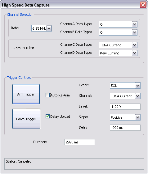
Figure 7: The High Speed Data Capture window
Two TUNA-specific Data Types are available in Channels C and D:
- TUNA Current: the average current over one tapping cycle.
- Raw Current: the instantaneous current.
NOTE: The default Channel C and D Data Types are Deflection Error and Height, respectively. Use the drop-down menus to select TUNA parameters. If you wish to retain your channel selections, Arm or Force the Trigger in the High Speed Data Capture window.
| www.bruker.com
|
Bruker Corporation |
| www.brukerafmprobes.com
|
112 Robin Hill Rd. |
| nanoscaleworld.bruker-axs.com/nanoscaleworld/
|
Santa Barbara, CA 93117 |
| |
|
| |
Customer Support: (800) 873-9750 |
| |
Copyright 2010, 2011. All Rights Reserved. |
Open topic with navigation