You are here: Experiment Guide > Imaging Modes > Applications Modules > PeakForce TUNA Software Selection

PeakForce TUNA Software Selection

  1. Click the Select Experiment icon in the NanoScope toolbar. This opens the Select Experiment window, shown in Figure 1.

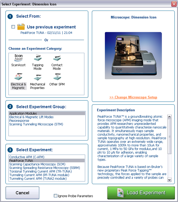
Figure 1: The Select Experiment, PeakForce TUNA mode, window.

  1. Select Electrical & Magnetic in the Experiment Category panel.
 
  1. Select Application Modules in the Experiment Group panel.
  2. Select PeakForce TUNA in the Select Experiment panel.
  3. Click the Load Experiment button.
  4. The Feedback, PF-TUNA and PeakForce control panels, shown in Figure 2, in the Scan Parameter list display the PF-TUNA control parameters.

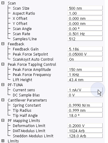
Figure 2: TUNA control parameters in the Scan Parameter list

 
  1. Set the appropriate gain (Current sens) in the PF-TUNA panel for the expected current range of your experiment. Refer to Table 1 to for details.


PF-TUNA Parameter Use with PF- TUNA
Current sens

Selects the gain of the TUNA sensor:

  • 20 pA/V = gain of 5x10¹⁰
  • 100 pA/V= gain of 1010
  • 1 nA/V = gain of 109
  • 2 nA/V = gain of 5x10⁸
  • 10 nA/V = gain of 108
  • 100 nA/V = gain of 107
DC Test Bias Provides an additional bias for the purpose of testing the TUNA sensor.
DC Sample Bias Selectable bias to chuck/sample.

Table 1: PF-TUNA Control parameters

 
  1. A window, shown in Figure 3, will open prompting you to set the Gain switch on the PeakForce TUNA module, shown in Figure 4. Set it to Hi for Current sensitivities of 20 pA/V, 100 pA/V or 1 nA/V and set it to Lo for Current sensitivities of 2 nA/V, 10 nA/V or 100 nA/V.

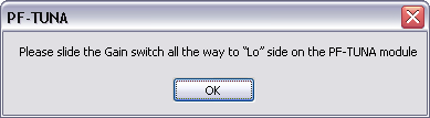
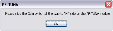
Figure 3: NanoScope gain switch messages

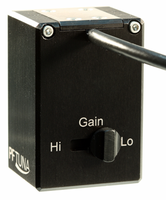
Figure 4: The PeakForce TUNA Gain switch

NOTE: Ensure that you have pushed the switch all the way to either the Hi or Lo Gain setting.
NOTE: Due to inherent mechanical characteristics of the specialized probe holder necessary for this imaging mode, reduced closed loop X IGain and Y IGain parameters are necessary.
  1. Select Calibrate > Scanner > X-Y... from the main menu. The OptoXY Closed Loop Calibration dialog will open.
  2. Set X IGain and Y IGain to 8.
  3. Click OK to close the window and continue with your experiment.

Ensure that you reset the parameters to their default values (12) when using the standard air tapping or TR holder.


www.bruker.com Bruker Corporation
www.brukerafmprobes.com 112 Robin Hill Rd.
nanoscaleworld.bruker-axs.com/nanoscaleworld/ Santa Barbara, CA 93117
   
  Customer Support: (800) 873-9750
  Copyright 2010, 2011. All Rights Reserved.