 PeakForce TUNA I-V Spectra
PeakForce TUNA I-V Spectra
PeakForce TUNA I-V Spectra
In addition to the imaging mode, PeakForce TUNA can also measure local current-voltage (I-V) spectra using the spectroscopy mode. In order to obtain I-V spectra, the imaging scan is stopped and the probe tip is held in a fixed location while the sample bias is ramped up or down. In spectroscopy mode, the feedback is switched to Peak Force and a constant peak force is maintained by the feedback loop while the sample bias is ramped. The resulting current through the sample is plotted versus the applied bias. The software can either record a single spectrum or average over multiple spectra. The higher bandwidth of the PeakForce TUNA module allows I-V curves to be taken at higher speeds; this expands the bandwidth of AC based dI/dV measurements, for instance, using the “Generic Lock-in” feature offered with the NanoScope V Controller.
I-V curves can also be taken using the Point & Shoot feature. The Point & Shoot feature offers the option of drawing a line or a box on an image, defining a number of points so that the AFM tip will automatically move to those locations to capture one or multiple I-V curves at each point. While this is a powerful automation feature, it often can be more useful to manually choose a few spots of interest at specific regions on the sample. Refer to Point and Shoot in the NanoScope Software Version 8 User Guide.
|
|
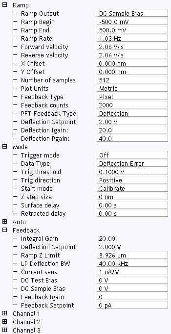
Figure 1: The PeakForce TUNA Ramp Parameter list window
| Parameter | Use with PeakForce TUNA |
|---|---|
| Ramp Output |
Select a TUNA parameter to ramp:
|
| Ramp Begin, Ramp End | The beginning and end points of a ramp. |
| Ramp Rate | All ramps are begin-end-begin cycles. Ramp Rate refers to one complete cycle. |
| Forward velocity, Reverse velocity | The ramp value from beginning to end, or end to beginning. |
| X Offset, Y Offset | Moves the probe tip to a different location. |
| Number of samples | The number of sample points per ramp (minimum 16, maximum 64,000 for low, < 0.31 Hz, Ramp Rates). |
| Plot Units | Metric or Volts |
| Feedback Type |
Ensures that the deflection feedback is ON during ramping. Settings:
|
| Feedback counts | Select 2000 for proper feedback. |
| PFT Feedback Type | Select Deflection. |
| Deflection Setpoint | Select a value. |
| Deflection Igain | Set to 20. |
| Deflection Pgain | Set to 40. |
Table 1: PeakForce TUNA: Ramp Controls Parameters in the Ramp Parameter list window
|
NOTE: Ramp Rate, Forward Velocity and Reverse Velocity are interdependent. Changing a velocity affects the overall Ramp Rate, and vice versa.
|
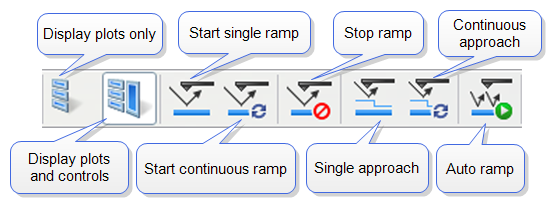
Figure 2: Toolbar Buttons: Start, Stop and Capture Ramp Curves
|
|
|
|
|
Trigger Mode enables limiting the current passing through a sample to protect it. See the Ramp > Mode panel (see Figure 3) for trigger parameters. Table 2 describes trigger parameter functions.
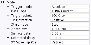
Figure 3: The PeakForce TUNA Ramp Mode panel
| Parameter | Use with PeakForce TUNA |
|---|---|
| Trigger Mode | Triggering is either Off, Absolute or Relative. For IV-spectra select Absolute to turn the trigger on (see following caution). |
| Data Type | For IV-Spectra, select TUNA Current for triggering on the current. |
| Trigger threshold | This sets the trigger value. For a current sensitivity of 1pA/V, select any value between +10pA and -10pA. For a current sensitivity of 10pA/V, select any value between +100pA and -100pA. |
| Trigger direction | See Trigger Direction |
| Start mode |
Start mode allows you to switch between the various force modes without returning to image mode. Range or Settings:
|
| Z step size | The change in tip height per step when using force step. |
| Surface delay |
Specifies a delay when the tip reaches the point closest to the sample. Range or Settings:
|
| Retracted delay |
Similar to Surface delay, this value specifies the duration of the delay when the piezo is at the top of the cycle (farthest away from the sample). Range or Settings:
|
| XY Move Tip Pos |
Three options are available for moving, in XY, from one point to another:
|
Table 2: TUNA: Mode Panel Parameters
Triggering requires specifying the Trigger Direction.
|
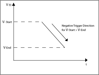
Figure 4: TUNA, SSRM: Negative Trigger Direction for VStart > VEnd
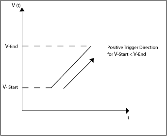
Figure 5: TUNA, SSRM: Positive Trigger Direction for VStart < VEnd
The Mode panel offers two more parameters that are used to independently add delay times at the end of a start-end ramp, or at the end of a complete start-end-start cycle (see Figure 6).
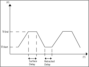
Figure 6: TUNA, SSRM: Delaying Ramps
| www.bruker.com | Bruker Corporation |
| www.brukerafmprobes.com | 112 Robin Hill Rd. |
| nanoscaleworld.bruker-axs.com/nanoscaleworld/ | Santa Barbara, CA 93117 |
| Customer Support: (800) 873-9750 | |
| Copyright 2010, 2011. All Rights Reserved. |