You are here: Experiment Guide > Imaging Modes > Applications Modules > TR-TUNA Software Selection

TR-TUNA Software Selection

  1. Click the Select Experiment icon in the NanoScope toolbar. This opens the Select Experiment window, shown in Figure 1.

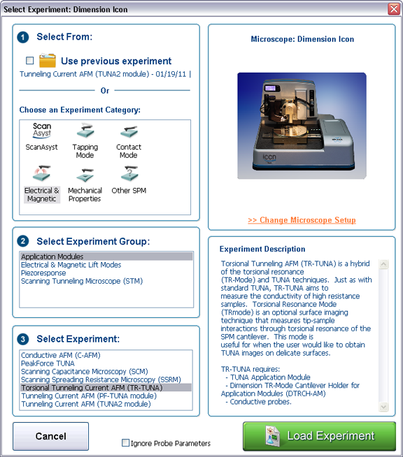
Figure 1: The Select Experiment, TUNA mode, window.

  1. Select Electrical & Magnetic in the Experiment Category panel.
 
  1. Select Application Modules in the Experiment Group panel.
  2. Select Torsional Tunneling Current AFM (TR-TUNA) in the Select Experiment panel.
  3. Click the Load Experiment button.
  4. The Feedback and TUNA panels, shown in Figure 2, in the Scan Parameter list display the TUNA control parameters.

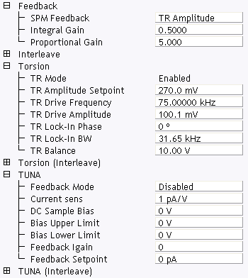
Figure 2: SCM control parameters in the Scan Parameter list

 
NOTE: Closed Loop TUNA and TR Mode are not available simultaneously. To use Closed Loop TUNA, you need to select TUNA as the Microscope Mode (not Torsion TUNA).

Tune

  1. Click the Setup icon in the Workflow toolbar to open the Setup window.
 
  1. Click the Manual Tune button in the Tune Cantilever panel, shown in Figure 3 to open the Cantilever Tune window.

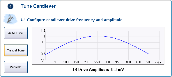
Figure 3: Click the Manual Tune button in the Tune Cantilever panel.

 
  1. Click Auto Tune in Tapping Mode.
  2. Clicking the Torsion radio button, shown in Figure 4, enables the torsion Cantilever Tune panel. Using the lateral sensors, C and D, of the quad photodetector, the Cantilever Tune panel, finds a peak with the highest amplitude within a frequency range specified by the user. Clicking Zero Phase sets the torsion phase to zero at this peak. The relative drive voltage applied to the two z-piezos is then automatically adjusted to maximize the RMS signal from the photodetector. This is called a Balance Tune. A Balance Tune can also be selected manually by clicking the More > Balance Tune button, shown at the bottom of Figure 4
NOTE: TR Balance runs from 0V (left) to 10V (right), with 5V giving each z piezo equal voltage.

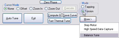
Figure 4: Torsion Auto Tune Controls

 
  1. After completing the Auto Tune, set Coupling Check to On. See Figure 5. The Coupling Check displays the photodetector A-B (bending) signal, allowing you to compare the A-B output to the C-D (torsion) output to ensure that a torsional resonance mode has been selected by the tuning procedure. When Coupling Check is On, the system switches TR Off so that the user is temporarily looking at the vertical amplitude, shown using the same scale as TR Amplitude, which allows the user to observe if the torsion peak is coupled to the tapping peak (TR Amplitude is not much greater than Tapping Amplitude).

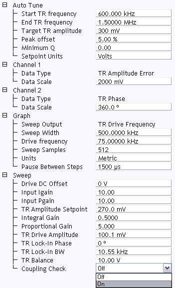
Figure 5: Set Coupling Check to On.

 
  1. After completing the Coupling Check, return to Image Mode by clicking Exit.


www.bruker.com Bruker Corporation
www.brukerafmprobes.com 112 Robin Hill Rd.
nanoscaleworld.bruker-axs.com/nanoscaleworld/ Santa Barbara, CA 93117
   
  Customer Support: (800) 873-9750
  Copyright 2010, 2011. All Rights Reserved.