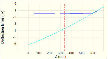
If a force volume image is uniform at all Z display values (that is, all slices), check the various display parameters first. The settings may be too high or too low. For example, if the Data Scale is much smaller (or larger) than the actual range of cantilever deflections at any Z position, then all the pixels at the Z position will be to the low (or high) end of the scale. The same effect occurs if Data Center fails to bring the measured forces into the Volume scale range. Adjust Data Scale and Data Center until the variation in forces is displayed.
If FV Channel/Z display is set too high, force curves appear as flat lines; if it is too low, the majority of force curves display flattened against one or the other extreme of Z position.
Check the color bar. If the contrast is too high, only the extremes of deflection show up in the force volume image. Changing the Color Table in Image Mode can reduce contrast (different color tables have different default contrast levels).
If Sensitivity was not set properly in Force Plot Mode, then force plot scaling is inaccurate.
If a trigger is being used, ensure that it is enabled, and vary Trig threshold to assure that the threshold deflection is large enough. If it is too low, only the noncontact portion of the curve is measured. For example, a 320 µm cantilever with a spring constant of 0.01 N/m oscillates with an amplitude of roughly 3 nm at room temperature. These oscillations and a 2 nm Trig threshold initiate the trigger almost immediately after beginning a scan.
All the interesting forces may be mapped to a single pixel of Z data; that is, the Z resolution is too low for the forces of interest. Trade off XY resolution (i.e., Force per line or Samples per line or both) for Z resolution (Number of samples) to alleviate the problem.
If no adjustment to display parameters creates a non-uniform image, perhaps there is no force variability in the scan area. Adjust Z scan start and Ramp size in the Z Scan panel to scan the regions of interest within the force curves. It may be necessary to return to Force Plot Mode to do this. If the probe cantilever is too stiff to respond to the forces present, replace it with a more pliant cantilever or use a higher Trig threshold.
 A Force Volume Image is Uniform