For surface potential microscopy (also called scanning Kelvin probe force microscopy, SKPFM) measurements, the feedback adjusts the DC voltage applied between the tip and sample to compensate their intrinsic potential difference. The DC voltage map across the surface thus reflects surface potential variations of the sample surface.
When the difference is perfectly compensated, the tapping oscillation amplitude of the metal coated AFM cantilever (excited by an AC bias field) approaches “0”—the very reason this technique is called a nulling technique. In doing so, the feedback uses the tapping amplitude and phase to determine whether to increase or decrease the DC voltage.
|
|
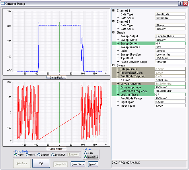
To facilitate setting the Phase parameter, NanoScope Version 8.15 software now features a Set Phase tool, which enables the user to determine the lock-in phase with a single click. |
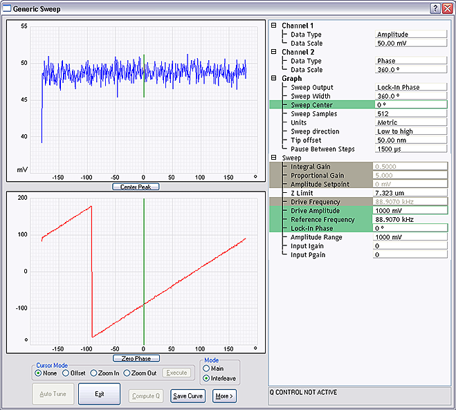
Generic Sweeps are taken on Interleave. In some cases, it is helpful to switch back and forth between Main and Interleave for the sweep parameters to take effect. Some inconsistency may occur—for instance, potential feedback may not actually be on when Input Igain and Input Pgain are non-zero.
Recall: Lock-In Phase depends on the mechanical properties of the cantilever. For cantilevers with resonant frequencies from 60–80 kHz (such as MESP, SCM-PIT, and FESP), use an interleave Lock-In Phase of 170 degrees. For cantilevers with higher resonant frequencies, increased electronics phase lag must be compensated. For cantilevers with resonant frequencies around 300 kHz (such as TESP, RTESP) an interleave Lock-In Phase near 130 degrees often works well.
| www.bruker.com | Bruker Corporation |
| www.brukerafmprobes.com | 112 Robin Hill Rd. |
| nanoscaleworld.bruker-axs.com/nanoscaleworld/ | Santa Barbara, CA 93117 |
| Customer Support: (800) 873-9750 | |
| Copyright 2010, 2011. All Rights Reserved. |
 Interleave Tuning Curve - Phase Lag
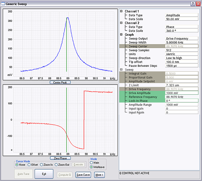
 Related Topics