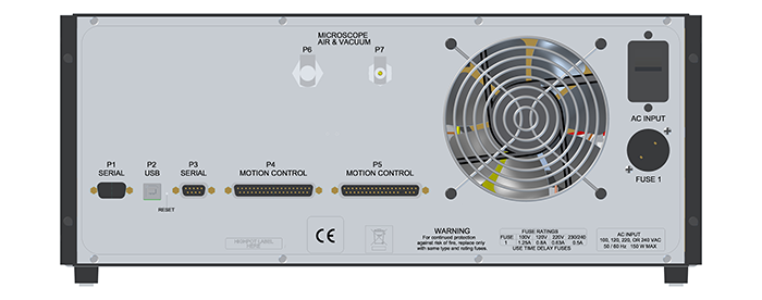
| Figure Reference | Cable | Part Number | Box | Function |
|---|---|---|---|---|
| 1 | AC Power | 466-000-004 | Power Strip | Dimension controller power |
| P6/P7 | Vacuum Hose Assembly | 860-000-012 | Dimension Icon | Vacuum and air supply |
| P1 | Serial Cable (6') | 464-000-024 | Computer | Serial communication with computer |
| P3 | Serial Cable | NanoScope V Controller | Crash protection | |
| P4 | 37-pin Cable | Dimension Icon | Motion control | |
| P5 | 37-pin Cable | Dimension Icon | Motion control |
Figure 1: Dimension Stage Controller - Rear View
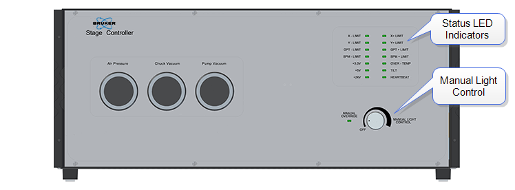
Figure 2: Dimension Stage Controller - Front View
| www.bruker.com | Bruker Corporation |
| www.brukerafmprobes.com | 112 Robin Hill Rd. |
| nanoscaleworld.bruker-axs.com/nanoscaleworld/ | Santa Barbara, CA 93117 |
| Customer Support: (800) 873-9750 | |
| Copyright 2010, 2011. All Rights Reserved. |