It is not uncommon for the diamond tips to pick up debris from the sample when indenting and, in particular, when scratching. Like a dull tip, a dirty tip may require more force to successfully indent or scratch. Also, a dirty tip can cause irregular (not triangular) indents to be made. Possibly, no indentation can be made, even using the maximum force available.
If the tip is dirty, the user should also notice a loss in the image resolution. A dirty tip, like a dull tip, will not resolve fine features. This becomes most apparent when comparing images before and after a nanoindentation operation; if the image has degraded noticeably, it is probably contaminated. To clean the tip, try the procedures below (listed in the order shown they should be attempted).
NOTE: It is useful to capture images before and after tip cleaning for comparison.
Tip Cleaning Procedures
- Indent on the Sample
Position the tip over a new section of the sample and perform multiple (3–5) indentations at the same location on the sample.
On harder samples, such as DLC (diamond-like carbon) films, limit the Trigger threshold to about 0.5 V. Hopefully, these moderate force indentations will knock the debris off the tip. Do not use larger forces than are necessary; large forces on very hard samples may cause damage to the diamond tip.
On softer samples, such as the gold film provided with the nanoindentation package, use a larger Trigger threshold such as 2.0 V. Performing indentations with large forces on a very soft sample may knock off the tip debris.
If the hardness of the sample is not known, use the gold sample provided. The gold sample is soft enough to insure that the diamond tip is not damaged, even with the largest indent force, during the tip cleaning procedure. The gold sample also has good topographic features to determine if the image resolution has improved.
If the tip has been successfully cleaned, the image resolution should improve.
NOTE: The
gold sample, provided with the nanoindentation option, is a gold film, used at
Bruker to test each indentation cantilever for tip sharpness, orientation, and indentation ability. The print-out contained in the nanoindentation package is an image of the gold sample, which was imaged using your indentation tip. The image contains indentations made using Trigger thresholds of about 0.4, 0.6, and 0.8 V. This image can be used by the user to test the indentation cantilever’s imaging and indenting ability. Simply engage on the gold sample and check if the image and indents are comparable to the print-out supplied.
- Indent on the Soft Gold Sample
In general, cleaning the tip by indenting is more successful on a soft sample with large forces than on a harder sample using moderate forces. Thus, if the sample is relatively hard, it may be helpful to engage on a soft sample, such as the gold film provided with the nanoindentation package, and try indenting as described above. Use a large Trigger threshold, about 2.0 V, and indent multiple times in the same location.
If the tip has been successfully cleaned, the image resolution should improve.
If the first attempt fails to clean the tip, offset to a new location on the sample and repeat above. This method is not always successful on the first attempt.
- Indent on the Soft Gold Sample with Increased Force
If methods A and B are unsuccessful, it may prove useful to make an indentation on the gold sample with even more force than possible in Indent mode. This should only be attempted if the previous two methods fail to clean the tip, and should only be carried out on the gold sample provided with the nanoindentation package, or a similarly soft sample.
- Engage the microscope in TappingMode.
- Set the Scan size to 0 nm. This halts the scanning and holds the diamond tip at a fixed location on the sample.
- Set the Amplitude setpoint to 0 V.
This causes the tip to be forced into the sample by the full extent of the Z piezo, causing a large indentation. The indentation force will be approximately five times larger than the maximum force possible in Indent mode. When the Z piezo is fully extended, the Z Center Position bar, located on the image monitor, should display “Limit”. Also, the line on the Z Center Position bar will move to the Extended side to show that the scanner is fully extended.
- Reset the Amplitude setpoint to its original value after the scanner has extended. This will cause the Z piezo to lift the tip away from the sample surface and return to TappingMode imaging. The Z Center Position should return to a position somewhere in the middle of its range.
- Offset to a new location on the sample and check if tip cleaning was successful.
Use an offset of about 5–10 μm in the X and/or Y direction (until the indentation that has just been made does not appear in the scan area). If the tip has been successfully cleaned, the image resolution should improve.
- Indent on Soft Gold Sample with Maximum Force
CAUTION: The following procedure can result in damage or destruction of the probe and should not be performed unless all other methods have failed.
If method C above is not successful, it may be helpful to further increase the indent force used for cleaning the tip. This procedure is similar to method C, except that the vertical stepper motor is used to maximize the range of the Z piezo prior to the tip cleaning indentation. Do the following in conjunction with method C, above:
- Engage the microscope on the gold sample using TappingMode.
- Select Motor > Step Motor from the Real-time menu to open the Motor Control panel.
- Set the SPM step size to ~0.5 μm.
- Click on the Tip Down button until the scanner is almost retracted.
The motor may not move the SPM until multiple steps of the motor are executed. Continue stepping the motor until the line on the Z Center Position bar moves to a position near the Retracted side. The Z Center Voltage, displayed near the Z Center Position bar, should decrease to approximately –200 V.
NOTE: The fully retracted Z Center Voltage is –220 V. This step provides the Z piezo with the largest range with which to push the tip into the sample, during the tip cleaning indentation. Now, the only limitation to the indentation depth is the trigger threshold which can be increased to make deeper indentations.
- Perform steps #2–5 in method C, above.
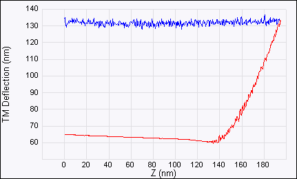
 Insufficient Force