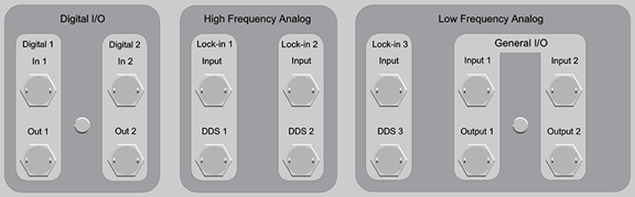
The NanoScope V Controller facilitates integration of SPM imaging with other laboratory equipment by providing the experimenter with numerous auxiliary input and output signal path options. Access to these features is clustered in the lower left of the front panel of the NanoScope V Controller, shown in Figure 1.
The auxiliary signal path options are:
Figure 1: Close-up of Connectors, Front of NanoScope V Controller
For example, a scan rate of 1 Hz generates 2 line-sync pulses per second, one for trace and one for retrace.
Refer toTable 1 for more detail concerning the auxiliary connectors.
| Connector Label | Connector Type | Purpose |
|---|---|---|
| Digital 1 and 2 | BNC, > 1 MΩ impedance | Bandwidth 5 MHz. See the Generic Lock-In section of the NanoScope Software 8.15 User Guide |
| Lock-In 1 and 2 | BNC, < 1 kΩ impedance | Inputs for user-supplied signals: range: –10 V to 10 V DC bandwidth: 500 Hz to 5 MHz |
| Lock-In 3 | BNC, < 1 kΩ impedance | Inputs for user-supplied signals: range: –10 V to 10 V DC bandwidth: 5 Hz to 50 kHz |
| Out 1 (EOF output) | BNC, > 1 MΩ impedance | TTL reference signal for image end-of-frame: negative-going pulse, +5 V to 0 V after every frame, up and down |
| Out 2 (EOL output) | BNC, > 1 MΩ impedance | TTL reference signal for image end-of-line: negative-going pulse, +5 V to 0 V after every trace and retrace |
| DDS 1, 2 and 3 (Lockin Ref. output) | BNC, > 1 MΩ impedance | Programmable (to 10 V) output |
| General I/O Input 1 and 2 | BNC, < 1 kΩ impedance | Inputs for user supplied signals: range: –10 V to 10 V DC bandwidth: DC to 10 kHz |
| General I/O Output 1 and 2 | BNC, > 1 MΩ impedance | Analog outputs that can be used to monitor selectable NanoScope V Controller signals. See Signal Access Software of the NanoScope Software 8.15 User Guide |
| www.bruker.com | Bruker Corporation |
| www.brukerafmprobes.com | 112 Robin Hill Rd. |
| nanoscaleworld.bruker-axs.com/nanoscaleworld/ | Santa Barbara, CA 93117 |
| Customer Support: (800) 873-9750 | |
| Copyright 2010, 2011. All Rights Reserved. |