Scale Differences between the NS III(a), IV(a) and the NS V Controllers
- For Dimension systems, Integral and Proportional Gains should be 5–10 times those used with a NS III(a) or NS IV(a) controller with the same type of scanner.
- Signals:
- The names of the SPM feedback Data Types have changed for the NS V controller. Deflection on the NS IV(a) is now called Deflection Error and Amplitude on the NS IV(a) is now called Amplitude Error.
- Deflection Error for the NS V controller is approximately equal to that of the Deflection on a NS IV(a) controller.
- Like the NS IV(a), the NS V Controller Deflection Error uses analog setpoint subtraction. The range of Deflection Error is ±(Deflection Limit/2). Deflection Setpoint + Deflection Error must lie in the range between ±(Deflection Limit/2).
- Amplitude Error for NS V Controllers is approximately 0.28 of the Amplitude on a NS IV(a) controller. When auto tuning, set your Target Amplitude and setpoint to be approximately 28% of the values used with a NS III(a) or NS IV(a) controller.
- Amplitude Error is defined as Amplitude - Amplitude Setpoint.
- The range of Amplitude Error is -Amplitude Setpoint to [(Amplitude Range)/2 - Amplitude Setpoint].
- The range of Amplitude is 0 to (Amplitude Range)/2.
- NS V Controller Drive Amplitude is one half [NS IV(a) Drive Amplitude].
- In TappingMode, Lock-In BW (bandwidth) should be set to be approximately one third of the [Drive Frequency] for maximum feedback response.
- When collecting an image, the Amplitude and Amplitude Error channels display larger amplitudes as brighter areas. This is opposite to the behavior of the NS IV(a) where darker areas in the image correspond to larger amplitudes. This will affect force modulation and TappingMode constant height images. They will be negatives of the images from the NS IV(a).
- Change the pgain/igain ratio for Dimension closed loop heads from 0.50 for NS IVa controllers to 0.30 for NS V controllers:
- Set XY Closed Loop to On. Select Calibrate > Scanner > X-Y to open the OptoXY Closed Loop Calibration window, shown in Figure 1. Set pgain/igain ratio to 0.125.
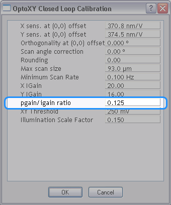
Figure 1: Set the pgain/igain ratio
| www.bruker.com
|
Bruker Corporation |
| www.brukerafmprobes.com
|
112 Robin Hill Rd. |
| nanoscaleworld.bruker-axs.com/nanoscaleworld/
|
Santa Barbara, CA 93117 |
| |
|
| |
Customer Support: (800) 873-9750 |
| |
Copyright 2010, 2011. All Rights Reserved. |
Open topic with navigation