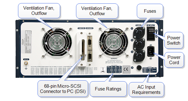
With all hardware connected, turn on power to the computer, then to the controller (back of NanoScope V Controller, upper right, shown in Figure 1) and then to the other components of the SPM system.
Figure 1: NanoScope V Controller Back Panel
If your system includes the workstation configuration, you may power up the system using the system power switch in the workstation cabinet. See Product Configurations for more information.
Verify the three power supply Light-Emitting Diodes (LEDs) on the front face of the NanoScope V Controller are lit (see Figure 2). The fourth LED blinks at 1 Hz when the FPGA inside the controller is loaded.
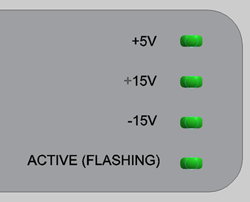
Figure 2: Power Supply LEDs on the Front of the NanoScope V Controller
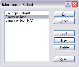
Double-click the Nanoscope icon on the desktop to commence software control over the SPM.
Confirm that the software and hardware match or enter details of any new SPM configuration before proceeding to Real-time Mode:
| www.bruker.com | Bruker Corporation |
| www.brukerafmprobes.com | 112 Robin Hill Rd. |
| nanoscaleworld.bruker-axs.com/nanoscaleworld/ | Santa Barbara, CA 93117 |
| Customer Support: (800) 873-9750 | |
| Copyright 2010, 2011. All Rights Reserved. |