When the relative Z position between the probe and sample is modulated, parasitic cantilever motions occur. These motions include free-cantilever oscillation after snapping off the surface, deflection triggered by harmonics of the piezo motion or viscous forces. This parasitic deflection, defined as the deflection signal variation when the tip is NOT interacting with the sample, limits the low force range of ScanAsyst operation. Low force control is the most important factor to achieve high resolution imaging and property measurements.
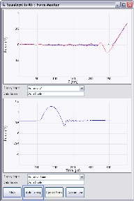
During peak force tapping operation, the Auto Config operation is used to analyze the parasitic deflection signal including its data pattern by comparing the known source of parasitic excitation, namely the cantilever resonance at pulling off, modulation harmonics and other system actuation sources. The signature of the interaction, in the shape of heartbeat signal, is extracted from the parasitic deflections. The recovered heartbeat signal becomes the interaction force curve plotted in the time domain.
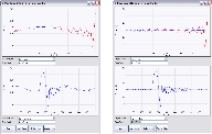
Figure 1 shows the heartbeat and force vs. Z curves of an image before and after Auto Config correction. The low frequency noise in the baseline has been removed.
(Hover over the image to view larger)
Figure 1: The heartbeat and force curves of an image before (left) and after (right) Auto Config correction
If your force vs. time curves show parasitic background noise or the force vs. height curve load and unload curves are overlapping due to background noise, click the Auto Config button, shown in Figure 2, to invoke the real-time pattern analysis algorithm that removes parasitic deflection reset the background and the sync distance.
(Hover over the image to view larger)
Figure 2: The Auto Config button
| www.bruker.com | Bruker Corporation |
| www.brukerafmprobes.com | 112 Robin Hill Rd. |
| nanoscaleworld.bruker-axs.com/nanoscaleworld/ | Santa Barbara, CA 93117 |
| Customer Support: (800) 873-9750 | |
| Copyright 2010, 2011. All Rights Reserved. |