You are here: Experiment Guide > Imaging Modes > Piezoresponse Force Microscopy > Piezoresponse Nanolithography with NanoMan V Software

Piezoresponse Nanolithography with NanoMan V Software

NanoScope software with the optional NanoMan V feature can also be used to polarize thin PZT films. Applying a high voltage to the tip (
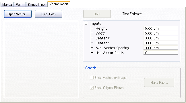
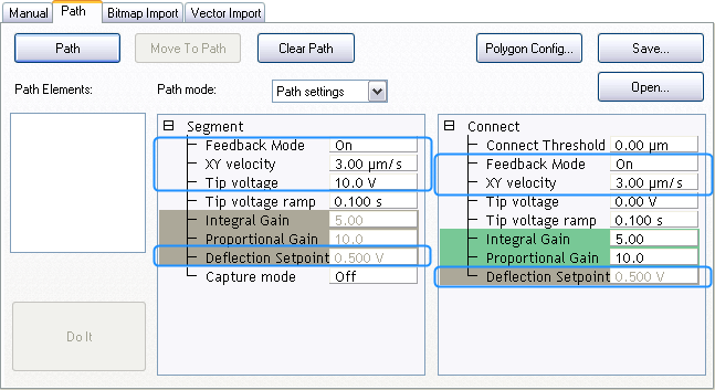
10 V) usually polarizes the film. NanoMan software enables the user to write custom paths and patterns as well as import bitmaps and vectors directly into the NanoMan interface. This section assumes basic familiarity with the NanoMan V interface. More information about the NanoMan software is available in Support Note 013-413-000.

NOTE: Bruker’s PPLN sample can not be polarized by low voltages ( 12 V). Consequently, use a piezoresponsive thin film for PFM Nanolithography.
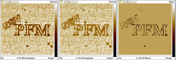
NOTE: NanoMan is an optional software that is available at additional cost. Contact your Bruker salesperson for pricing.
  1. Click the Select Experiment icon to open the Select Experiment window.
  1. Select the following:
    • Experiment Category: Other SPM
    • Experiment Group: Nanomanipulation
    • Select Experiment: Piezoresponse Force Lithography
 
  1. Click Load Experiment.
  2. Using the workflow toolbar, proceed through microscope setup using the steps outlined for PFM Optimized Vertical Domains Operation.
NOTE: Interleaved scanning does not work with NanoMan.
  1. Select the NanoMan Icon in the workflow toolbar to open the NanoMan interface.
 
  1. Click on Vector Import to open a tab that allows you to import vectors exported as a windows metafile (files with *.wmf extension).


Windows metafiles can be created by many software packages including Microsoft VisioTM and PowerpointTM.

  1. Click on Open Vector to open a browse window to import a *.wmf file.

If the Show vectors on image box is selected, the imported vector superimposed on the image will now be visible in the NanoMan window:

 
  1. To modify the voltages used for polarizing the PZT film, click on the Path tab:


The Segment parameters define the values to be used for drawing the vector, whereas the Connect parameters define values to be used for everything else in the image.

  1. Ensure that the Segment and Connect parameters are set for voltage polarizing nanolithography (these are default values):
    1. Feedback Mode: On (to perform polarizing of the sample using tip bias)
    2. XY velocity: to 3 μm/sec.
    3. Gray out the Deflection Setpoint to use the Deflection Setpoint from the Scan Parameters (to do this, click on the word "Deflection Setpoint" to change the highlighting from Green to Gray).
  2. In the Segment parameters list, set Tip voltage to 10 V.

 
  1. To perform polarizing, return to the Vector Import tab and click Do It.

The software will indicate the various operations it is performing and display a message Nanoman is currently walking a path. The tip position will be updated.


You may need to experiment with different tip velocities, deflection setpoints and voltage values to ensure that the entire region is polarized by the bias.

Below is a pattern polarized using NanoMan V Software on a thin PZT film with 12 V tip bias.


www.bruker.com Bruker Corporation
www.brukerafmprobes.com 112 Robin Hill Rd.
nanoscaleworld.bruker-axs.com/nanoscaleworld/ Santa Barbara, CA 93117
   
  Customer Support: (800) 873-9750
  Copyright 2010, 2011. All Rights Reserved.