Load a Probe for Fluid Imaging with the Dimension Scanner
The probe is held in a small pocket on the bottom side of the fluid probe holder by a gold-plated stainless steel wire. The probe holder stand has three docking stations where different probe holders may be mounted. Use the docking station that has a small wire between two of the sockets:
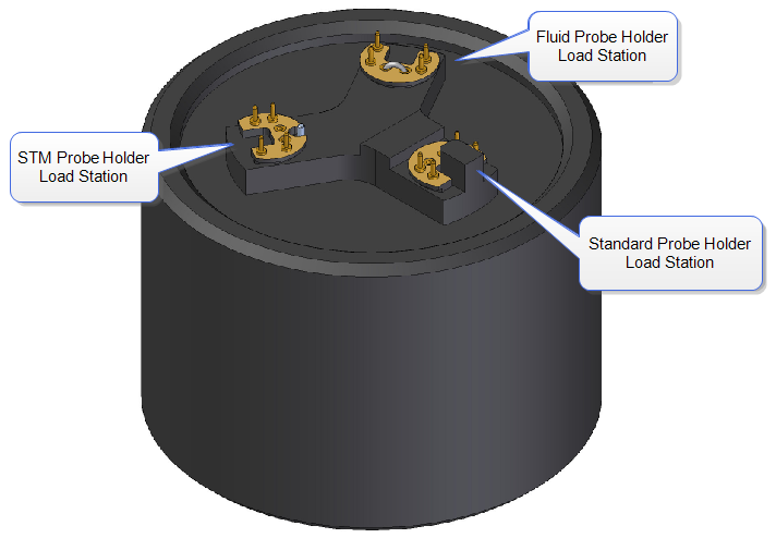
Figure 1: The Dimension Icon probe holder stand
The steel wire is held against the cantilever substrate by a leaf spring (clip release button) mounted on the top of the probe holder:


Figure 2: High Efficiency Direct Drive Fluid Probe Holder (Version 1)


Figure 3: High Efficiency Direct Drive Fluid Probe Holder (Version 2)
To mount a probe in the holder:
- Turn the holder over so that the clip release button and four sockets are facing down.
- Plug the holder onto the fluid probe holder docking station of the probe holder stand (see above).
- Grip the probe holder by the edges and gently push down on the holder.
NOTE: When pushing down on the holder, the steel wire in the docking station will press on the leaf spring to raise the spring-loaded probe clip that will hold the substrate in the mounting groove.
- With the wire raised, use tweezers to slide a probe under the wire and into the pocket.
- Check that the cantilever substrate is set squarely against one side of the pocket and flush against the back.
CAUTION: Avoid scratching the probe holder's glass surface with the tweezers or the cantilever substrate, especially in the area under the cantilever itself.
- Gently lift the probe holder off the docking station.
NOTE: When removing the probe holder from the docking station, the leaf spring should pull the gold wire tight against the cantilever substrate.
- Check that the probe is held firmly by the wire.
Install the Fluid Probe Holder
- Check that there is sufficient clearance between the bottom of the SPM Scanner and the sample.
NOTE: The cantilever probe position extends roughly 1 mm further towards the sample with the fluid probe holder over the standard air probe holder.
- If the height of the scanner needs adjustment, use one of the following methods:
- Navigate and raise the probe with the Z motor control, or the trackball
- Microscope > Step Motor > Tip Up
- Withdraw
- Gently unplug any probe holder attached to the base of the scanner.
- If necessary, lift the scanner out of the dovetail to allow for easier access to the base of the scanner.
- Pull the probe holder straight off to prevent bending any of the pins on the probe holder or scanner cap.
- Fit the fluid probe holder onto the four pins of the scanner cap.
NOTE: The four sockets on the probe holder will only align with the pins on the scanner cap when the cantilever probe points to the left of the microscope.
- Set the scanner back into the dovetail and lock into place by releasing (turn counterclockwise) the knurled scanner clamp screw, located at the upper-right of the Z-stage, until the thread is just tightened.
Once the fluid probe holder is in place, make sure to install the protective skirt before attempting to image.
 Related Topics
| www.bruker.com
|
Bruker Corporation |
| www.brukerafmprobes.com
|
112 Robin Hill Rd. |
| nanoscaleworld.bruker-axs.com/nanoscaleworld/
|
Santa Barbara, CA 93117 |
| |
|
| |
Customer Support: (800) 873-9750 |
| |
Copyright 2010, 2011. All Rights Reserved. |
Open topic with navigation