Atomic Force Microscopy (AFM)
Developed in 1986 by Binning, Quate, and Gerber as a collaboration between IBM and Stanford
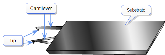
University, the atomic force microscope (AFM) grew out of the and today is by far the more prevalent of the two. Unlike STMs, AFMs can be used to study insulators, as well as semiconductors and conductors. The probe used in an AFM is a sharp tip, typically less than 5 μm tall and often less than 10 nm in diameter at the apex. The tip is located at the free end of a cantilever that is usually 100–500 μm long.
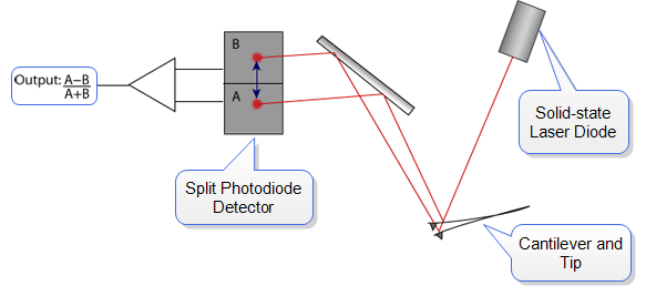
Forces between the tip and the sample surface cause the cantilever to bend, or deflect. A photodiode detector measures the cantilever deflections as the tip is scanned over the sample, or the sample is scanned under the tip. The measured cantilever deflections allow a computer to generate a map of surface topography. Several forces typically contribute to the deflection of an AFM cantilever. To a large extent, the distance regime (i.e., the tip-sample spacing) determines the type of force that will be sensed:

Figure 1: The effect of tip-to-sample distance on the force interaction between tip and sample
The forces between the tip and sample change as the separation distance changes. As the tip and the sample are gradually brought together, their atoms begin to weakly attract each other. This attraction increases until the atoms are so close together that their electron clouds begin to repel each other. This electrostatic repulsion progressively weakens the attractive force as the separation continues to decrease. The total force goes through zero and finally becomes positive (repulsive).
Most AFMs use optical techniques to detect the position of the cantilever. In the most common scheme, a light beam from a laser diode bounces off the back of the cantilever and onto a position-sensitive photo-detector (PSPD). As the cantilever bends, the position of the laser beam on the detector changes. The ratio of the path length between the cantilever and the detector to the length of the cantilever itself produces amplification. As a result, the system can detect sub-Ångstrom vertical movement at the free end of the cantilever, where the tip is located.
Variations on this basic scheme are used to measure topography as well as other surface features. There are numerous AFM Modes. Each is defined primarily in terms of the type of force being measured and how it is measured.
 Related Topics
| www.bruker.com
|
Bruker Corporation |
| www.brukerafmprobes.com
|
112 Robin Hill Rd. |
| nanoscaleworld.bruker-axs.com/nanoscaleworld/
|
Santa Barbara, CA 93117 |
| |
|
| |
Customer Support: (800) 873-9750 |
| |
Copyright 2010, 2011. All Rights Reserved. |
Open topic with navigation
 and today is by far the more prevalent of the two. Unlike STMs, AFMs can be used to study insulators, as well as semiconductors and conductors. The probe used in an AFM is a sharp tip, typically less than 5 μm tall and often less than 10 nm in diameter at the apex. The tip is located at the free end of a cantilever that is usually 100–500 μm long.