The Image analysis displays the selected image with color-coded height information in a two-dimensional perspective. Image analysis is the default NanoScope analysis such that when an image is initially opened it is always rendered in Image.
|
|
The Image analysis displays the selected image with color-coded height information in a two-dimensional perspective. Image analysis is the default NanoScope analysis such that when an image is initially opened it is always rendered in Image. |
To process an image, you must open an image file. This can be done by:
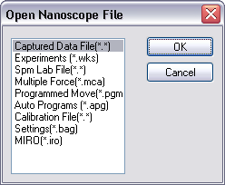
Figure 1: Open NanoScope File dialog box
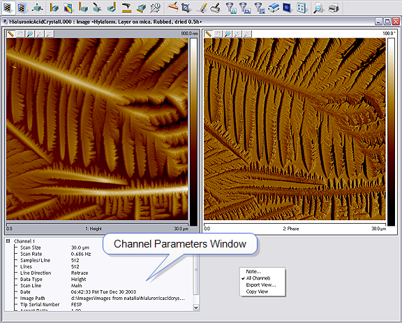
Figure 2: Image for Processing
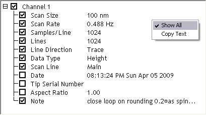
Figure 3: Channel Parameters Hide / Show Selection
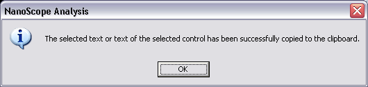
Figure 4: Dialog indicating text has been copied to the clipboard
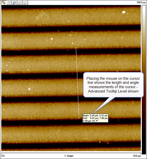
Figure 5: Cursor length and angle measurement
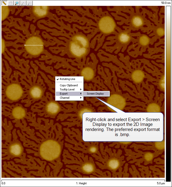
Figure 6: Export Menu
| Parameter | Description |
|---|---|
| Scan Size | Length of each scan line for a given image |
| Scan Rate | Number of scan lines per second |
| Samples/Line | Number of sample data points per scan line |
| Lines | Selects the number of lines to scan in a frame |
| Line Direction | Trace (left to right) or Retrace (right to left); defined when the image was originally taken |
| Data Type | Data Type is defined by the channel selection when the image was originally taken |
| Scan Line | Choose Main or Interleave; defined when the image was originally taken |
| Date | Time and date scan was taken |
| Tip Serial Number | Serial number of tip; must be manually entered by operator when the image was originally taken |
| Aspect Ratio | Image ratio of width to height |
| Note | User added, description of file |
| www.bruker.com | Bruker Corporation |
| www.brukerafmprobes.com | 112 Robin Hill Rd. |
| nanoscaleworld.bruker-axs.com/nanoscaleworld/ | Santa Barbara, CA 93117 |
| Customer Support: (800) 873-9750 | |
| Copyright 2010, 2011. All Rights Reserved. |