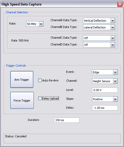
The High Speed Data Capture window, shown below, allows you to capture and store many signals. To open the High Speed Data Capture window, click Capture > High Speed Data Capture.
Note: The High Speed Data Capture function is not available on all microscopes, e.g. the Dimension Icon-PI, supported by NanoScope version 8 software.
Channels A and B can capture data at 6.25 MHz and 50 MHz while channels C and D capture data at 500 kHz. Channels A and B capture Vertical and Lateral Deflection respectively. Data capture of those channels may also be turned Off.
Table 1shows the available data types are available for capture.
| Channel | Data Type | Frequency |
|---|---|---|
| A and B |
Vertical Deflection Lateral Deflection |
6.25 MHz 50 MHz |
| C and D |
Height Signal Sum X sensor Y sensor Z sensor Amplitude Phase TM Deflection Deflection Error Friction Z Feedback Output Input 1 Input 2 Input 3 X Scan Y scan |
500 kHz |
| Trigger Control | Description |
|---|---|
| Arm Trigger |
Arm Trigger begins monitoring for the trigger conditions to be met and starts data acquisition into the FIFO buffer. This button toggles to Disarm Trigger when the trigger is armed. |
| Disarm Trigger | Disarm Trigger stops data acquisition and stops monitoring for a trigger event. |
| Auto Re-Arm | The Auto Re-Arm check box causes the trigger to be re-armed after the data acquisition is completed. If Auto Re-Arm is not checked, the trigger will be disarmed after the data acquisition has been completed. |
|
Force Trigger |
The Force Trigger button triggers data collection. |
|
Event |
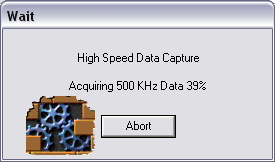
The trigger Event drop-box allows you to trigger on an Edge, EOL (End of Line), EOF (End of Frame) or None. When the trigger is armed and a trigger Event occurs (or, if the trigger is forced), an Abort box, shown in Figure 1, giving you the ability to abort the data acquisition appears. Note: If Event = None, you must Force Trigger to begin data acquisition.
|
|
Channel |
The Channel drop-box allows the following data types to be used as a trigger:
|
|
Level |
Select the trigger Level at which you wish to begin acquiring data. |
|
Slope |
You may trigger on either a Positive or Negative Slope. |
|
Delay |
Trigger Delay, if Positive, specifies the amount of time between when the trigger conditions are met and when data capture begins. If Negative, Delay specifies the amount before the trigger conditions are met that data capture begins. |
|
Duration |
The time Duration of data that is saved. |
Table 2: Trigger Controls Panel
The high speed data capture status is displayed in the status panel at the bottom of the HSDC window. Captured file names have a suffix of .hsdc
The High Speed Data Capture (HSDC) function in the Point and Shoot view, shown in Figure 2, allows you to mark a spot for data collection. This can be operated in two modes:
In either mode, you must set the capture conditions in the High Speed Data Capture window before acquiring data.
Force Trigger: forces a trigger at the marked point regardless of the preset trigger conditions.
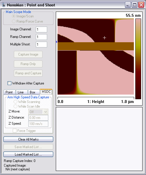
Figure 2: Point and Shoot - High Speed Data Capture
| www.bruker.com | Bruker Corporation |
| www.brukerafmprobes.com | 112 Robin Hill Rd. |
| nanoscaleworld.bruker-axs.com/nanoscaleworld/ | Santa Barbara, CA 93117 |
| Customer Support: (800) 873-9750 | |
| Copyright 2010, 2011. All Rights Reserved. |