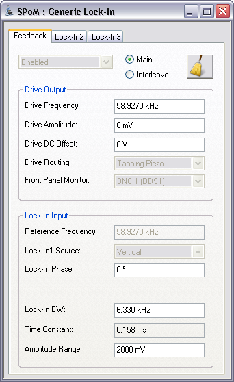
The Generic Lock-In GUI, brings together all of the controls associated with the use of the three internal lock-in amplifiers of the NanoScope V BioScope II Controller into a single panel, shown in Figure 1. The tabs along the top of the main panel are used to access the interface for individual lock-ins.
Figure 1: The Generic Lock-In, shown configured for TappingMode imaging. The DDS 1 output is routed to the Tapping Piezo and the lock-in input is set to monitor the vertical photodetector signal.
When calling the lock-in panel with the microscope set to TappingMode, the primary lock-in selection tab is labelled Feedback. In addition the parameters Drive Routing, Lock-In1 Source and Lock-in Enable/Disable are disabled and greyed out. This prevents the user from inadvertently mode switching while scanning and using the primary lock-in for feedback.
When calling the lock-in panel with the microscope set to Contact mode the primary lock-in selection tab is labeled Lock-In 1. All of the lock-in parameters including those disabled for tapping mode are enabled for user selection. Lock-in changes are unable to change the microscope mode while scanning in Contact mode.
STM, Tapping/TR, TR/Tapping, Dynamic Friction and Piezo Response modes are not yet supported by the Generic Lock-In.
Below the lock-in selection tabs are controls, shown in Figure 2, that enable the lock-in enable setting parameters for both main and interleave modes. Each of the three lock-in panels has all of the controls necessary to use that lock-in independent of the state of the other lock-ins. Each panel also has a button that allows the user to rapidly access the NanoScope Generic Sweep function, shown in Figure 3.

Figure 2: Buttons to enable/disable the lock-in and to set parameters for main and interleave modes.
The Generic Sweep button takes the user to the Generic Sweep window and populates fields based on values in the calling lock-in panel. Clicking the More button of the Generic Sweep window allows the user to toggle between the enabled lock-ins without leaving the Generic Sweep window.

Figure 3: The Generic Sweep window may be accessed from the lock-in panel.
The Drive Output panel, shown in Figure 4, contains all of the controls to configure the output waveform of the DDS including frequency, amplitude, DC offset and the signal routing.
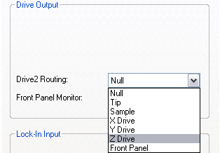
Figure 4: The Drive Output panel
The Harmonic Drive Output option, available for Lock-In 2, locks in on a user-selected harmonic (1–25) of the drive (DDS 1) signal. This enables you to lock in on higher (than the fundamental) frequency modes of the cantilever. You must set Lock-In 1 (Feedback) to Enabled and select set Lock-In 2 to Harmonic.
Sets the frequency of the corresponding DDS output and the reference for the lock-in input.
Sets the zero-to-peak amplitude of the DDS output.
Applies a DC shift to the AC bias.
Note: The maximum output voltage of the DAC is +/–10 Volts. Ensure that the DC offset plus the AC Drive Amplitude is less than 10V to avoid clipping the output waveform.
Sets the output destination for the drive signal. Options are Tapping Piezo, Tip, Sample, X Drive, Y Drive, Z Drive, Front Panel (Lock-In 2)and Null. When the output is selected as Front Panel, the output is routed to the DDS 2 BNC on the front panel of the NanoScope V Controller. When the output is selected as Null, the output is not routed but allows a reference signal to be generated and the lock-in used for inputs.
The Lock-In Input panel, shown in Figure 5, contains all of the controls to configure the inputs to the lock-in.
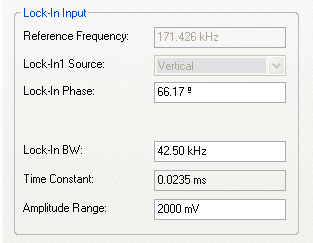
Figure 5: The Lock-In Input panel.
Duplicates the frequency from the Drive Output panel.
Selects the input source to the lock-in amplifier. Options are Vertical Photo-detector, Horizontal Photo-detector, Application Module and Front Panel.
Sets the phase offset between the detected signal and the reference. Three buttons below the parameter display add/subtract 90° or Zero the current phase.
Sets the lock-in bandwidth for the lock-in input.
Calculated from the lock-in bandwidth as (1/lock-in BW).
| www.bruker.com | Bruker Corporation |
| www.brukerafmprobes.com | 112 Robin Hill Rd. |
| nanoscaleworld.bruker-axs.com/nanoscaleworld/ | Santa Barbara, CA 93117 |
| Customer Support: (800) 873-9750 | |
| Copyright 2010, 2011. All Rights Reserved. |