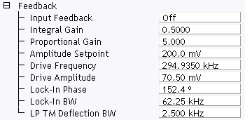
The Feedback parameters, shown in Figure 1, allow for monitoring the signals between the NanoScope Controller and the cantilever. These signals adjust the Setpoint, Oscillation frequency, Drive Voltage, Z response for surface tracking, and output voltages. The purpose of the Feedback controls is to maintain a constant setpoint (deflection, amplitude, or current) in the Feedback Loop for tip/sample control and tracking optimization. Parameters listed in the Feedback panel depend on the microscope selected and the Mode.
Figure 1: Feedback panel in Expanded TappingMode
| Parameter | Description |
|---|---|
|
Z Modulation (Fluid TappingMode only) |
Allows the user to add the drive oscillation signal to the Z piezo voltage. This parameter is used to set up fluid cell oscillation in any Dimension system for Fluid TappingMode. Range or Settings:
The desired Drive Amplitude and Drive Frequency voltages (Cantilever Tune) need to be set for Fluid TappingMode operation. |
|
SPM Feedback |
Selects the signal to be used for tip feedback according to the selected Microscope Mode parameter (Other panel). For Contact AFM, the choice defaults to Deflection; however, for TappingMode, you may select either TM Deflection or Amplitude. STM offers two choices of feedback: Linear and Log. Range or Settings:
See also Optimizing the STM Feedback Parameters. |
|
Input Feedback |
Controls Frequency Modulation (MFM or EFM) and Surface Potential. |
|
Integral Gain |
Controls the amount of integrated error signal used in the feedback calculation. Range or Settings:
Gain settings vary, depending upon the scanner used, the sample and scanner sensitivity. Typical Integral Gain Ranges:
|
|
Proportional Gain |
Controls the amount of the proportional error signal used in the feedback calculation. The Proportional Gain term in the feedback calculation has equal gain at all frequencies; therefore, it has a dominating effect over the Integral Gain for high frequencies (scan rates). Range or Settings:
|
|
Setpoint |
The meaning of this parameter depends on the operating mode of the microscope as follows: Amplitude Setpoint (TappingMode)—defines the amplitude of the cantilever oscillation signal to be maintained by the feedback loop. (Range: 0.00 to 10.00V) Deflection Setpoint (Contact Mode)—Controls the deflection-signal level used as the constant desired voltage in the feedback loop. (Range: -12.00 to 12.00 V) Current Setpoint (STM)—Controls the constant current maintained by the feedback loop. (Range: 0.0 to 100.0nA) |
|
Drive Frequency (TappingMode and Force Mode only) |
Selects the oscillation frequency applied to the piezoelectric crystal that vibrates the cantilever. Range or Settings: 0.00 to 250MHz The Center Frequency is adjusted with the Cantilever Tune command to find the resonance frequency of the cantilever. The maximum cantilever oscillation amplitude occurs at its resonant frequency. The software sets the Drive Frequency equal to the current Center frequency value when the OK button in the Cantilever Tune control panel is pressed. |
| Drive Phase (TappingMode and Force Mode only) | Selects the phase of the drive voltage applied to the piezoelectric crystal that vibrates the cantilever. |
| Drive Amplitude (TappingMode and Force Mode only) |
Selects the amplitude of the drive voltage applied to the piezoelectric crystal that vibrates the cantilever. Range or Settings: 0.00 to 20.00V The Drive Amplitude is also adjusted with the Cantilever Tune command. Increasing the Drive Amplitude increases the cantilever-oscillation amplitude. The cantilever-oscillation amplitude is increased to an appropriate level with the Cantilever Tune command. In AutoTune, the Drive Amplitude automatically adjusts to get a cantilever oscillation (rms amplitude) equivalent to the user’s Target amplitude. |
|
Bias |
Controls the sign and magnitude of the bias voltage applied to the sample. Range or Settings: -10.00 to 10.00V When used with STM, typical settings for the Bias voltage parameter are 20 to 100mV for conductive samples and up to several volts with poorly conducting samples. Positive settings of the Bias voltage item correspond to negative current (electrons) tunneling from the tip into the sample on heads with the Bias applied to the Sample or Tip. |
|
Analog 1, 3, 4 |
This voltage has no effect on the operation of the standard microscope, but is useful in custom applications. Range or Settings: 10.00 to 10.00V. |
|
Aux Lockin |
Directs an external input signal through the auxiliary lock-in amplifier. |
|
Drive Phase |
The phase of the AC bias signal applied to stimulate piezoresponse. |
|
Lockin BW |
The bandwidth of the effective bandpass filter centered on the TTL level reference frequency (i.e., the cantilever drive frequency in the NanoScope Controller) used by the main lock-in amplifier. |
|
Lateral 16x Gain |
Increases the lateral gain 16 times. This should be set to Disabled for most applications. Range or Settings: Disabled, Enabled |
| www.bruker.com | Bruker Corporation |
| www.brukerafmprobes.com | 112 Robin Hill Rd. |
| nanoscaleworld.bruker-axs.com/nanoscaleworld/ | Santa Barbara, CA 93117 |
| Customer Support: (800) 873-9750 | |
| Copyright 2010, 2011. All Rights Reserved. |