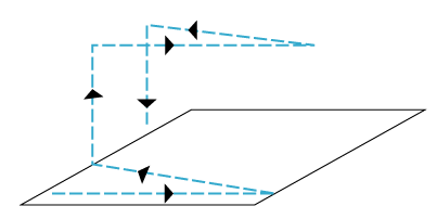
Figure 1: Interleave Lift Mode
| Parameter | Description |
|---|---|
|
Specifies the tip’s height above the sample surface during interleaved scans. This parameter is in effect ONLY when the Interleave mode parameter is set to Lift. See Figure 2. Range or Settings: XXµm (Scanner dependent) The maximum meaningful value of the parameter depends on the Z voltages applied in the Main scan line and the maximum voltage that the system can output. The maximum voltage that can be applied to the piezo is ±220V. It will be lower if the Z voltage is restricted by the Z Limit parameter. |
|
|
Lift Start Height |
Specifies the height that the tip is to be lifted above the sample surface at the start of each interleaved scan. Generally, this parameter serves to lift the tip clear of any contamination layers present on the sample before assuming its Lift Scan Height during interleaved scans. This parameter is in effect ONLY when the Interleaved mode parameter is set to Lift. This parameter defines an offset from the Z voltage, or height, applied to the piezo on the Main scan line. See Figure 3. Range or Settings: XXµm (Scanner dependent) |
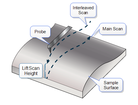
Figure 2: Lift Scan Height Illustrated
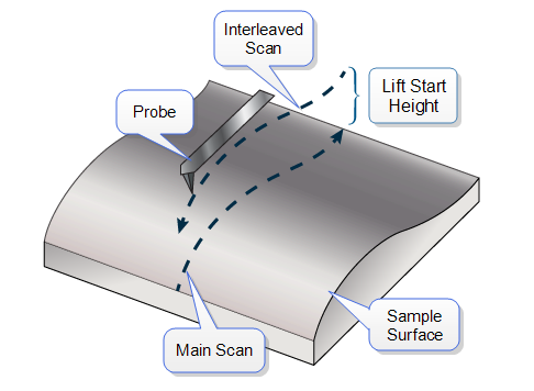
Figure 3: Lift Start Height Illustrated
This value can be left at zero for TappingMode and STM. It is generally only used for Contact AFM to break the tip free of the adhesive force produced by the water layer before settling to the final tip height.
The tip will go through this height at the start of every lifted scan line, then proceeds to the lift scan height for the rest of the scan line.
Several parameters (e.g. Z modulation, SPM Feedback, etc.) are highlighted by a dark gray or green background. Dark gray indicates that the parameters are coupled with the equivalent values in the Feedback panel. By selecting (left-click) the Interleave parameters, the grey field turns green, indicating that the Feedback and Interleave parameters are decoupled and the value in those parameters will be used as feedback during the Interleave scan line. See Figure 4.
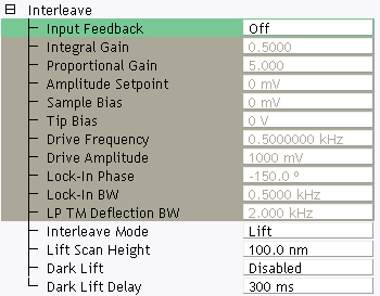
Figure 4: The Interleave Panel
| Parameter | Description |
|---|---|
|
Input Igain |
Integral gain for Frequency modulation. Controls the feedback loop that uses phase electronics. |
|
Input Pgain |
Proportional gain for Frequency modulation. Controls the feedback loop that uses phase electronics. |
Table 1: Special Interleave parameters
| www.bruker.com | Bruker Corporation |
| www.brukerafmprobes.com | 112 Robin Hill Rd. |
| nanoscaleworld.bruker-axs.com/nanoscaleworld/ | Santa Barbara, CA 93117 |
| Customer Support: (800) 873-9750 | |
| Copyright 2010, 2011. All Rights Reserved. |