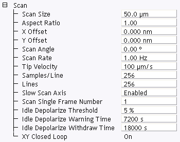
The Scan panel, shown in Figure 1, includes parameters influencing piezo movement and data acquisition, as well as the ability to execute non-square scans. This panel is probably the most frequently used panel, as it controls what type of scan to run, how large the scan is, its angle, scan rate, and number of samples per scan line.
Figure 1: Scan Panel Parameters, Contact in Expanded Mode
| Menu Item | Description | ||||||||
|---|---|---|---|---|---|---|---|---|---|
|
Scan size |
Determines the size of the scan by controlling the voltage applied to the X and Y piezos. Range or Settings:
The units of this parameter are volts if the Units parameter (Other panel) is set to Volts. The units are linear distance (nm or µm) if the Units parameter is set to Metric. See also Scan View Parameters Tips |
||||||||
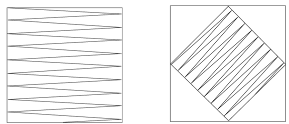
| Aspect Ratio |
Controls the width-to-height size ratio of scans. Set the Aspect Ratio to 1.00 for square scans. An Aspect Ratio of 2.00 yields scanned images having width equal to twice the height. Range or Settings: (depends upon the number of scan lines) 1 to 256.
Figure 2: Aspect Ratio example |
||||||||
| X offset, Y offset |
Controls the center position of the scan in the X and Y directions, respectively. Range or Settings: ±220 V; ± XX µm (dependent on Scan Size and scanner). |
||||||||
| Scan Angle |
Controls the angle of the X (fast) scan relative to the sample. Range or Settings: 0 to 359° (Any angular value can be entered with the keyboard). Changing this parameter can dramatically affect the quality of images due to tip effects (tip side wall angle). Setting this parameter to a setting besides 0 or 90° may reduce the maximum allowable Scan Size 10–20 percent due to corner constraints (see Figure 3).
|
||||||||
| Lines |
Selects the number of lines to scan in a frame. The Lines parameter reduces resolution along the Y axis. It also speeds imaging (or frame rate) and reduces the size of the resulting image file. Range or Settings: 2 to 1024. The maximum number of lines may be limited by the value for Samples/Line. |
||||||||
| Tip velocity |
Velocity of the tip (in µm/s) as it scans over the surface. When Tip Velocity is changed, the Scan Rate adjusts automatically. |
||||||||
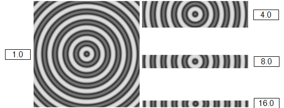
| Samples/Line |
Selects the number of sample data points per scan line. When this parameter changes, the number of scan lines per image (Lines) are automatically adjusted to maintain the same ratio between the samples/line and lines per image. Range or Settings: 32 to 16384. This setting influences the memory size of captured files and image resolution (see Table 1).
Table 1: File Size/Samples per line NOTE: Samples/line should be kept at 512 or higher for high resolution scans. To increase the frame rate (rate at which complete images are generated), the Lines parameter should be reduced. When the Lines parameter is reduced, file sizes in Table 1 are reduced accordingly
|
||||||||
| Slow Scan Axis |
Allows the slow scan to be disabled, causing the fast scan to be repeated continuously at the same position. This means that the image displays the same line continuously. Images may be presented either as “true” X-Y renderings of the sample surface (Enabled), or as “stretched” single-line scans of length equal to the Scan Size (Disabled). Range or Settings:
NOTE: Disabling the Slow Scan Axis and viewing the Scope display is a convenient way of setting the Feedback Gain parameters.
The advantage of using the Slow Scan Axis > Disabled parameter is to emphasize one area (line) to adjust the SPM parameters. For example, an area of the image that appears fuzzy (suggesting SPM parameters are not optimized for the sample). Disable the Slow Scan Axis, view the Scope trace, and reconfigure scan parameters to optimize the scan. NOTE: Setting the Slow Scan Axis parameter to Disabled stops the slow scanning of the piezo, but does not stop the movement of the Realtime display in Y. Lines are replicated in the Y direction.
|
| www.bruker.com | Bruker Corporation |
| www.brukerafmprobes.com | 112 Robin Hill Rd. |
| nanoscaleworld.bruker-axs.com/nanoscaleworld/ | Santa Barbara, CA 93117 |
| Customer Support: (800) 873-9750 | |
| Copyright 2010, 2011. All Rights Reserved. |