- Stop the main pump and load-lock pump using the switches in the rack marked "Main Chamber" and "Load Lock". Do NOT switch off the power ("Mains Power").
- Unscrew the knob holding the top lid of the main chamber in place; the pressure increases during the ventilation and might go above atmospheric pressure otherwise.
- Move the rate sensor to the middle of the chamber; by default, the rate sensor is touching the wall such that the lid cannot be opened otherwise. The rod used for positioning the rate sensor should be pointing straight towards you when standing in front of the system.
- When the chamber has reached atmospheric pressure, open the top lid of the main chamber. To minimize water vapor to enter the chamber, let some nitrogen flow through the chamber by opening the valve on your lower left when standing in front of the system.
- At a certain pressure, all power supplies with one exception are turned off; the extra DC power supply in the bottom of the rack must be turned off manually.
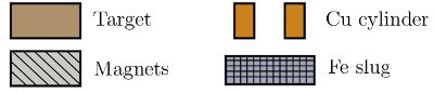
- There are eight guns in the chamber, numbered from one to eight. Number one is the gun at the twelve oÇclock position when standing in front of the chamber, followed by guns two to seven going clockwise around the chamber ending with gun number eight in the middle. Up to four guns can be configured for magnetic materials; the guns that are configured so at the moment are marked on a schematic fastened on the side of the rack.
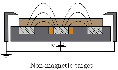
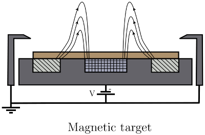
- If a magnetic target is to be mounted, a gun configured for magnetic materials must be used. In these guns, the middle magnet has been replaced by an iron slug so that the magnetic field lines can penetrate the target better. For the same reason, a magnetic target should have a thickness of three millimeters instead of six (standard for non-magnetic targets).
- Non-magnetic materials can be sputtered in magnetic guns; however, this is not recommended since the rate will be higher and the target will not last as long.
- If the shutter and chimney needs cleaning, or the new material is sensitive to contamination, start by disconnecting the flexible coupling from the shutter. Then unscrew the chimney (two long screws) and remove the shutter, chimney, and ground shield.
- Use the appropriate L-shaped hex-key for removing the wire hinge; the small yellow and black screwdriver is a bit rounded at the tip which eventually will destroy the screw.
- If the shutter and chimney do not need cleaning, or the new material is not sensitive to contamination, one can start by unscrewing the chimney (two long screws) and then tilt the combined shutter-chimney unit over and place it upside down on the neighboring gun without disconnecting the flexible coupling.
- Magnetic targets should be 2 inches in diameter and 0.125 inches (≈3 mm) thick, while non-magnetic targets should be 2 inches in diameter and 0.250 inches ( ≈6 mm) thick.
- Targets consisting of an insulating material or a semiconductor should have a copper backing plate to improve the heat conduction during deposition. The total thickness, target material plus backing plate, should be 0.250 inches ( ≈6 mm).
- Remove the ground shield.
- Remove the clamping ring by unscrewing the four screws.
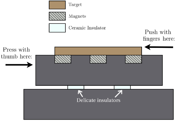
- It can be difficult to remove the target if it is a
magnetic material in a magnetic gun. Often, the only way to
do this is to slide the target sideways until your fingers
can reach underneath and pivot the target up onto its
edge. During the sliding action, it is very important not to
exert a torque on the ceramic feedthroughs between the
bottom ground and the top part of the gun. The location of
these ceramic insulators can be seen on the cross section
sketch below. By pressing a thumb against the side of the
gun and dragging/sliding the target in the opposite
direction using the fingers, this torque is minimized.
The clamping
ring can be used to get a better grip on the target while
performing this sliding action.
- After having removed the target, check how much material is left by measuring the depth of the circular groove on it with a caliper.
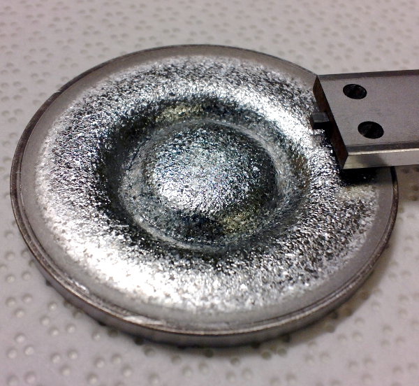
A used sputter target, magentic iron, end of caliper to the right. - See step no. 6 if the guns magnetic configuration needs to be changed.
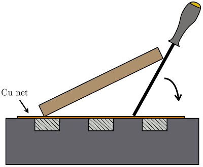
- A copper net should be placed underneath the new target to improve the heat conduction; cut a new one if the present one looks old and damaged.
- Placing a magnetic target should be done carefully; the
magnetic force can be strong and it is easy for a piece of
the glove to get stuck underneath the target. To prevent
this, one can make use of a screwdriver; first place the
target on its edge, then use the screwdriver to slowly lower
the target down onto the copper net, without using any
fingers. See figure below.
- Since magnetic materials are thinner, an adapter ring should be placed between the target and clamping ring.
- When replacing the clamping ring, make sure that the screws are tightened evenly; the plasma is very sensitive to the distance between the clamping ring and ground shield.
- Use a magnet, placed inside a glove, to remove any flakes on the outside of the gun before replacing the ground shield. By placing the magnet inside a glove, any flakes can be removed by simply removing the glove.
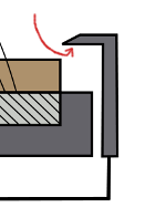
- Replace the ground shield after having checked its interior for flakes or loose material. Also look at the inside edge of the opening (the part closest to the target during deposition, see figure above) so that there isn't a too thick layer of sputtered material; if the ground shield has been used for a long time without cleaning, a thick layer of material forms on the inside edge, decreasing the distance between target and ground shield. This will eventually affecting the ability to strike a plasma.
- This is necessary if a non-mangetic target needs to be used in a gun configured for magnetic materials or vice versa.
- In a gun configured for magnetic materials, the center magnet has been replaced by an iron slug. We have four such slugs. The difference between a normal gun and one configured for magnetic materials is shown the figure above.
- Use the magnetic tool (black elongated magnet) to remove the middle magnet and the copper cylinder surrounding it.
- The iron slug has a long screw sticking up in its middle to make handling easier.
- Place the iron slug in the middle hole and remove the screw.
- To remove an iron slug from the center of a gun, fasten the screw in the center and pull it straight out; it might be necessary to use a tool to get a better grip.
- When placing a magnet in the center, make sure its polarity opposes that of the surrounding magnets. That is, if all the surrounding magnets has a north pole pointing upwards, the middle magnet should have its south pole pointing upwards, and vice versa.
- When done, check the operation of the shutter by opening and closing it a few times. This is especially important if the flexible coupling has been removed.
- Before evacuating the chamber, measure the resistance between the target and ground shield using a multimeter; it should be in the range of a few megaohms. If it is only a few ohms, there is a flake somewhere on the inside of the ground shield. If the resistance between the target and the bottom ground is still ohmic, even with the ground shield removed, there could be a flake in the small gap where the ceramic insulators are located; see the cross section sketch.
- For insulating materials, the resistance can be measured from underneath the chamber, between the center pin and outer part of the coax-cable connected to the gun.
- Close the top lid on the chamber.
- Close the nitrogen flow through the chamber by closing the valve on your lower left when standing in front of the system.
- Start the main pump and load-lock pump using the switches in the rack marked "Main Chamber" and "Load Lock".
- Move the rate sensor back to its original position.
- There are one RF power supply connected to a three-way switch-box and two DC power supplies of which one is connected to a three-way switch box; in total 7 cables, 3 RF and 4 DC. Thus, there will always be one gun with no cable connected.
- Insulating materials must be sputtered using an RF power supply.
- Metals can be sputtered using an RF power supply, but the rate is going to be much lower; better to use DC power if possible.
- In "System Configure", make sure the correct materials are written down and that the cable positions and valve positions are correct.
- Never press close when exiting the configuration screen. If you do, the main valve closes and the main chamber starts loosing vacuum.
- Wait until the pumps are up to speed (833Hz for the main pump and 1500Hz for the load-lock pump) and the main chamber has reached a pressure of ≈10-5 Torr.
- Strike a plasma at 30 mTorr using not more than 35W. Sometimes it can be tricky to strike an RF plasma; it might be necessary to first strike a DC plasma.
- Common reasons for why it will not work and the solution:
- Flakes shorting the gun. Chamber needs to be opened and flakes removed.
- The matching box used for RF-sputtering is in manual mode. Change it into automatic mode.
- The matching box used for RF-sputtering can sometimes get stuck at low values. Change to manual mode, then adjust the two values so that they are closer to the middle, i.e. 50% and 50%, then change back to automatic mode and try again.
- The DC power supply is stuck. Turn the power supply off, wait a moment, then turn it back on.
- The clamping ring has been tightened unevenly. Chamber needs to be opened and the clamping ring tightened evenly.
- Not enough Ar gas enters the chimney, indicated by the need to open the shutter in order to strike a plasma. The chamber needs to be opened and the gap between shutter and chimney adjusted.
- There might be impurities or an oxide layer on top of the target preventing a DC plasma. To prevent this, change cables and sputter for a while using an RF plasma, then change back.
- Cable is not fastened correctly. Check the cable.
- Cable might be hooked up to the wrong gun. Check the cable and the software configuration.
- If the software indicates a plasma, but no plasma can be seen, it might be the wrong shutter thats being opened. Check the software configuration.
- Make sure the rate monitor is against the wall of the chamber, and not in the way of the heater lamps.
- To make sure a large area is heated, adjust the position of the heater lamps so that they are as high as possible.
- Make sure the sample holder is in the load-lock and not inside the chamber.
- Start a heating process that heats to 250C for 12 or 15 hours.
- If making a new layer from scratch, remember to first set the main valve to its open position (in the programmed layer); it is set to closed by default.
- After one night of baking, the main chamber pressure should be down to 2 - 5 × 10⁻⁸ Torr.