Edwards Auto 306 service mode

In this mode, using the password, you can manipulate all valves and pumps individually.

Warning! Please note you have to know exactly what you are doing!
You can easily cause harm to the pumps and valves!


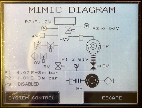
Schematic over the system. All components are shown active or passive, pumps running or not, valves open or closed, voltages from vacuumeters, etc.
List of components:
  • Top empty square = main vacuum chamber
  • RP: Roughing pump
  • TP: Turbo pump
  • RV: Roughing valve
  • BV: Backing valve
  • HVV: High vacuum valve
  • AV: Vent valve
  • P1: Pirani gauge for backing pressure
  • P2: Priani gauge for chamber pressure
  • P3: Penning gauge for chamber pressure, here not active due to too high pressure in the chamber.
At the lower left are the pressure values displayed, converted from the voltages. The roughing pump is running (shown in black) and the P1 gauge is showing 4 × 10⁻³ mBar, normal for a rotary vane oil pump.


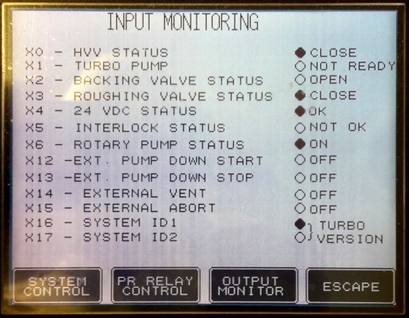
Here status of all the sensor switches are shown. This is for dislpay only, you cannot set anything from this screen.


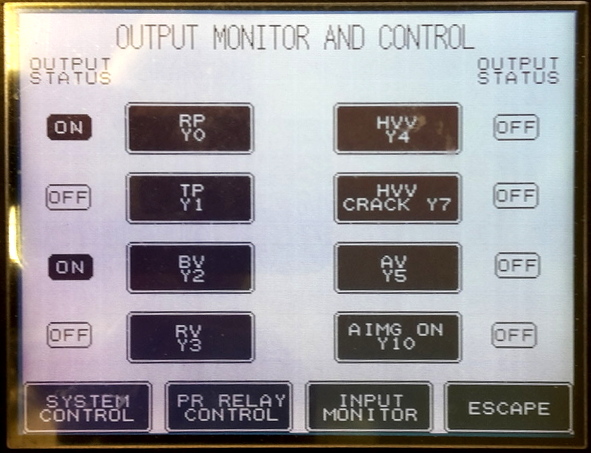
This is the part where you can cause real harm to the system. Be careful! You have to know in advance which order to activate the items.

Here is shown the output control signals from the controller. Be very carful here, you can start and stop the pumps, open/close the valves in any order. Please take care!
  • RP = Roughing pump start/stop
  • TP = Turbo pump start/stop
  • BV = Backing valve open/close
  • RV = Roughing valve open/close
  • HVV = High vacuum valve open/close. This is the valve between the turbo and the main chamber.
  • HVV CRACK = High vacuum valve open a little, used during pumpdown of chamber.
  • AV = Vent valve, letting nitrogen into the chamber up to atmosphere.
  • AIMG ON = Turn on Penning gauge, i.e. apply high voltage to Penning gauge, should only be done at good vacuum.


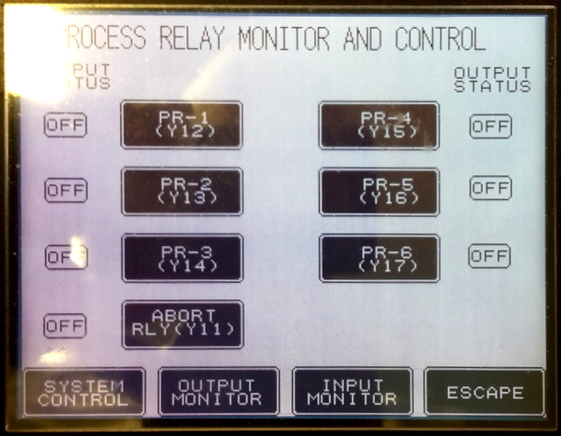
At the time of this writing we have no information about this.


Anders Liljeborg Nanostructure Physics, KTH.