Platinum deposition using Ebeam on AFM tips.

Anders Liljeborg, 2014-05-12


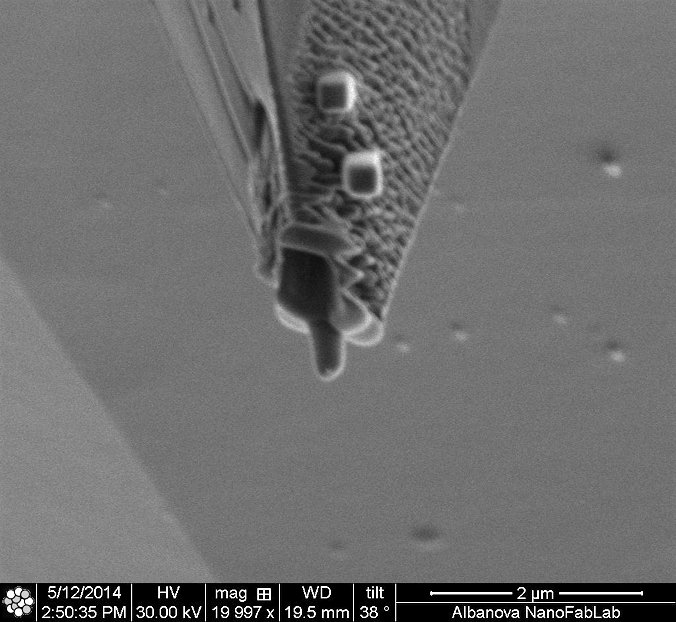
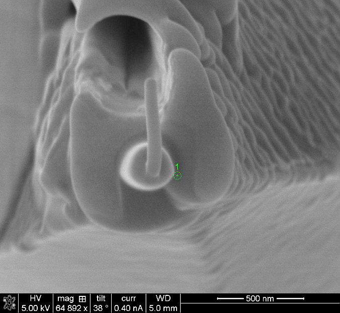
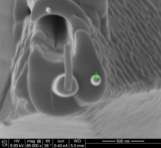
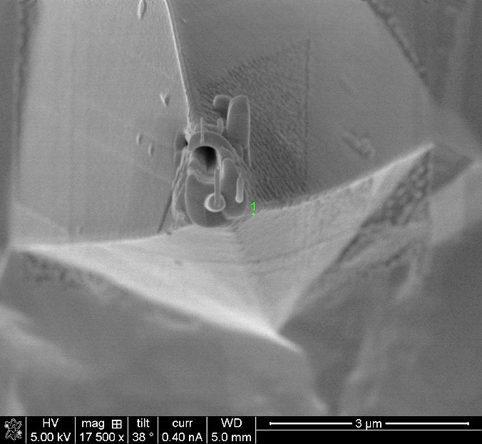
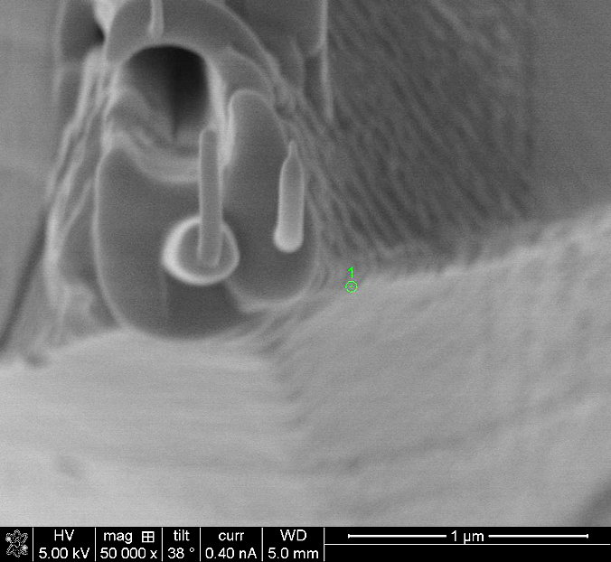
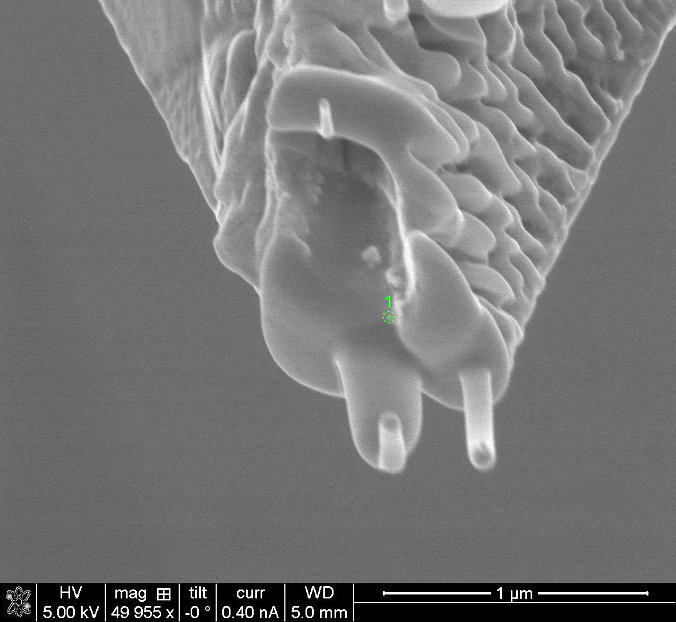
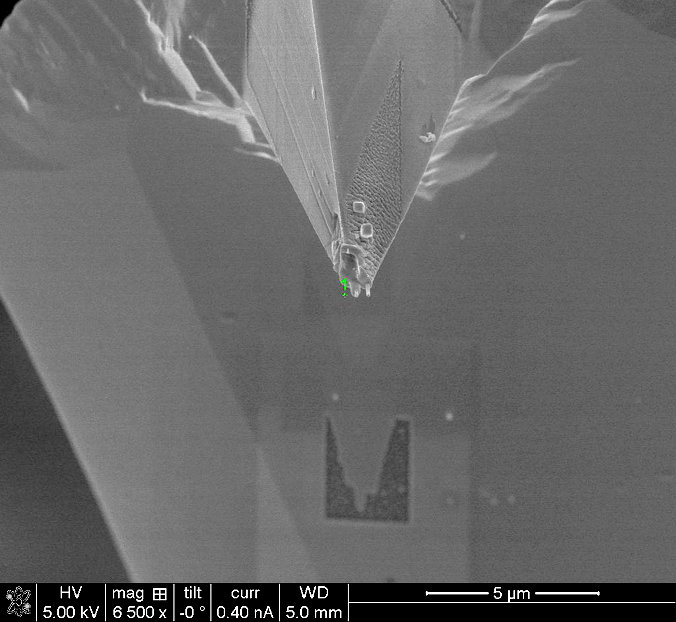
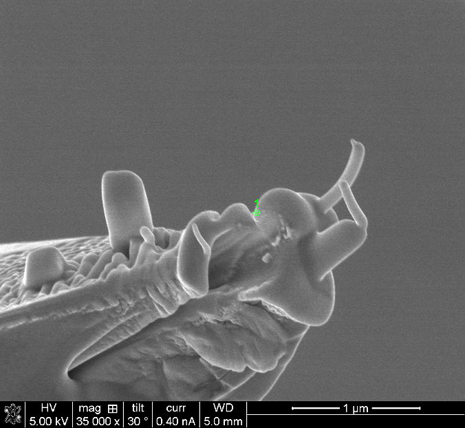
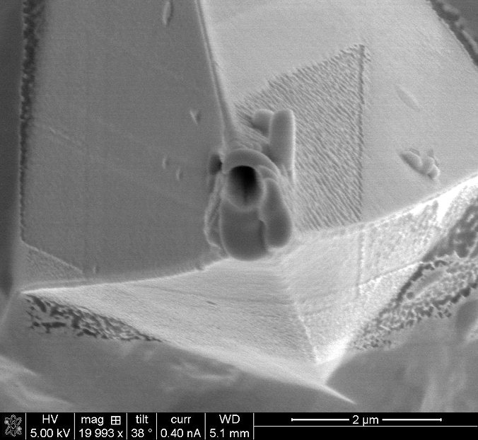
This is before any more e-beam depositioning. The tip and cantilever has been repositioned so that the e-beam is directed straight onto the tip, same direction as the ion-beam in the previous trials. I.e. the AFM-tip is now imaged straight from above.


Here a 200 nm circle with a nominal height of 5 µm has been deposited.


To get a quick view from the side I took one image with the ion-beam, 10 pA, 30 kV. Unfortunately I did not measure the height of the deposited tip, but it is less than nominal 5 µm.


Here is a 50 nm (nominal dim.) pillar deposited on top of the previous 200 nm pillar. This was set to 30 µm nominal height to make sure there was a pillar.


A view from the side using the ion-beam shows a very small pillar.


But! Taking a picture with the e-beam afterwards shows that the pillar was bent by the ion-beam image scanning.


Here another pillar is made to the right of the previous one. Also 50 nm nom. diam. and 30 µm nom. height.


Here is a side view using the ion-beam for image scanning, 10 pA, 30 kV.


Further scanning to adjust the focus shows that the right hand pillar is shrinking due to ion-beam milling.


But in fact it seems more to be bent than eroded.


A close up.


Here is the picture taken from a different angle. Note that tilt is 0° but the cantilever is mounted on a 45° sample holder.


Overview of tip and cantilever. Note shadow on cantilever from previous imaging with the ion-beam.


Tip with the different pillars seen from yet another angle.

Note the two leftmost square pillars. They were made with e-beam. The left most one was made with 17 kV and same nominal height as the next one done with 5 kV. Seems like 5 kV is more efficient for depositioning.


Anders Liljeborg Nanostructure Physics, KTH.