Service: Replace ion source and BAA in Nova 200 ion column

Anders Liljeborg, Jonas Applefeldt, 2014-09-03

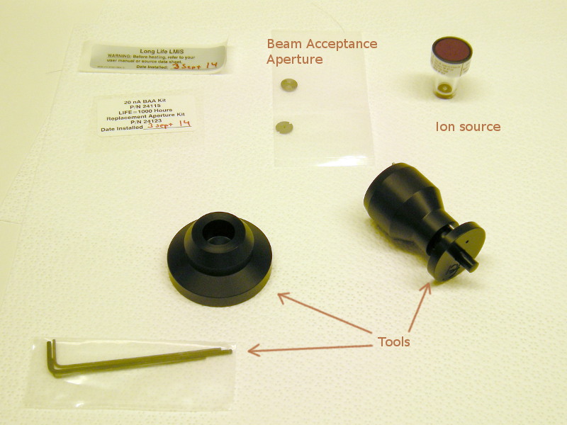
This is a very brief description of how to replace the ion source and the Beam Acceptance Aperture (BAA). It was done with short notes while Jonas was doing the actual work.
  1. Login is as "customerservice"
  2. Start "Test I gun".
  3. Set whole ion-column to power down.
  4. Take off covers on ion-column.
  5. Loosen screws, take off top cover.
  6. Remove the Hi Voltage connector carefully, do not use much force.
  7. Prepare by bring out the new ion Ga+ source and BAA from refrigerator.
  8. There is a plastic bag with adaptors/holders/tools for replacing the source and BAA, take care of that.
  9. Run "TST MOLVacuum", Action = "Vent I-column".
  10. Release the four black adjustment knobs on the outside of the column, they are 90° apart.
  11. There are four quarter inch screws, their outer heads are loosened, but wait for full ventilation of the column.
  12. Remove the coaxial-contact cylinder on the right side of the column.
  13. When venting is complete, take out the complete holder, including the white isolator.
  14. Remove central metal holder from isolator.
  15. Turn the metal holder upside down, so backside with two small hex-screws and the contact pins for the source are visible.
  16. Remove the two hex-screws
  17. Carefully remove the old source.
  18. Use one of the tools to insert the new source into the holder. Extreme care must be taken not to touch the tip of the source onto anything!
  19. Fasten the backside of the holder with the two small hex-screws.
  20. Put the metal holder back onto the isolator body in position so it fits with mounting holes and the two peripheral dents fitting the other holes in the isolator.

Replacement of BAA.

The BAA is positioned below the source, it is mounted inside the chamber, not on the source holder.
  1. Loosen the outer three hex-screws around the periphery of the holder for the BAA. Do not remove the screws!
  2. Using a tweezer, rotate the holder so it can slide over the screw heads through the larger part of the elongated screw holes.
  3. Place the holder on a clean-room wipe with the three smaller screws facing up.
  4. Remove the three smaller hex-screws.
  5. Lift off the top cover of the holder.
  6. Remove the old BAA and mount the new.
  7. Remove the old gasket???? and replace with the new?????
  8. Fasten the top of the holder with the three small hex screws.
  9. Insert the holder in the column using a tweezer, slide the big part of the outer holes over the screw heads still in the column.
  10. Rotate the holder so the small part of the holes come under the screw heads.
  11. Fasten the outer screws.

Mounting the ion-source holder

  1. Carefully put back the holder in the same position as it was.
  2. Fasten it with the four quarter inch screws.
  3. Carefully put back the Hi Voltage connector. The inner red isolator tubes are quite flexible and can go into the wrong hole. Do not use excessive force! If there is mechanical resistance when inserting the connector, one of the isolated contact pins have gone the wrong way. Take out the connector and start over again.
  4. Fasten the Hi Voltage connector with its mounting screws.
  5. Mount the unit with the co-axial connector on the right side of the column.

Pumping down, conditioning the column

  1. See to it that "Auto conditioning" starts.
  2. During pump down "BPVi" should be closed.
  3. I-col IGP should start at about mid 10-7 to low 10-7.
  4. Complete pump down may take one-two days, the IGP may have to be restarted a couple of times.

Adjusting the ion-column

  1. Load a standard sample, chip with matrix of crosses.
  2. Start using the 20 nA aperture (largest).
  3. Use adjustment "110 - Aperture alignment".
  4. Wobble the focus and fine tune using the four black knobs that were loosened at the beginning of this procedure. Adjust so that the image is centrally rotating, there should be no sideways or up/down movement of the image.
  5. All four black knobs must press on the holder when adjustment is finished.
  6. Cancel adjustment "110".
  7. Move to a new cross on the sample. This cross must be used for all adjustments of all the apertures.
  8. Start adjustment "210"
  9. Set Beam Shift to zero.
  10. Adjust the aperture position using the small knobs on the outside of the ion column, located under the gray cover below the column.
  11. Zoom to a 10 µm scale-bar.
  12. Start with the 0.1 nA aperture.
  13. Check several adjustments in one go by changing focus and stigmation. If the image is steady (no sideways/up-down motion) then all adjustments for this apertures are ok. You can switch to next aperture.
  14. Check in order 50 pA, 30 pA, 10 pA, 1 pA, i.e. decreasing currents from the starting aperture.
  15. Then use 300 pA aperture and upwards in aperture sizes.
  16. Work fast. For larger apertures (larger currents) the sample cross wears out fast. Do not use all the adjustment functions, use the trick above to see if the adjustments are already ok.
  17. Lower magnification means less wear on the cross on the sample.
  18. You must not change cross during this complete adjustment procedure!
  19. For the larger apertures use lower magnification, 30 µm, 50 µm scale-bar.
  20. Check Ion beam current for the different apertures when beam is blanked. It will show which apertures are worn, i.e. have higher current than the nominal.
  21. For the 20 nA aperture the "AperPos" does not matter. Ion Beam current readout is 22 nA for this session, this is normal.
  22. For lower acceleration voltages you make a new alignment "210". This may work only for some apertures.


The parts necessary for the replacement of the ion source and the BAA.
  • BAA and gasket (top center).
  • Plastic container for ion-source (Ga++) (top right).
  • Hex-keys, special adaptors for the ion-source holder and the BAA-holder.


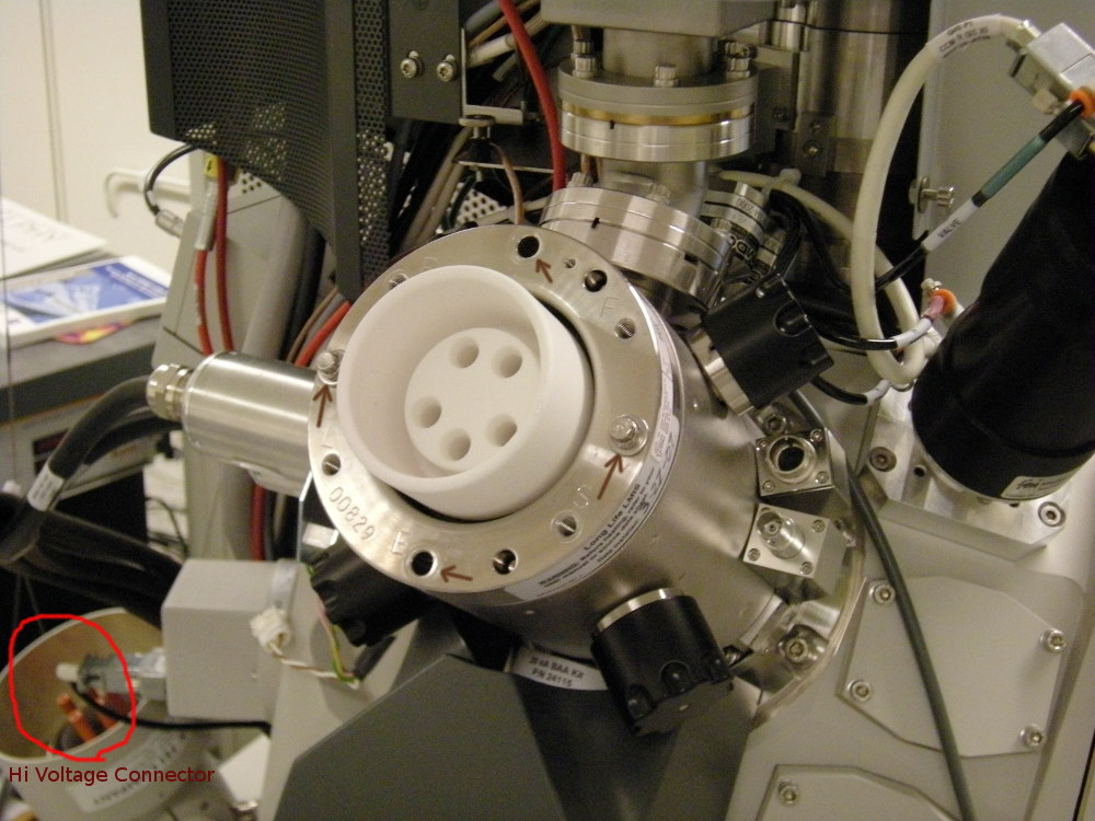
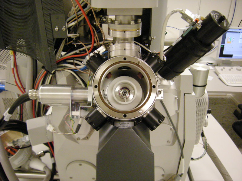
The ion column with the high voltage connector removed. The four 4 inch screws are indicated with brown arrows. Two of the screws (top and bottom ones) are already removed.
The high voltage connector is laying facing upwards at the far left.
The co-axial connector is free at the right side of the column.
Three of the four black adjustment knobs are clearly visible.


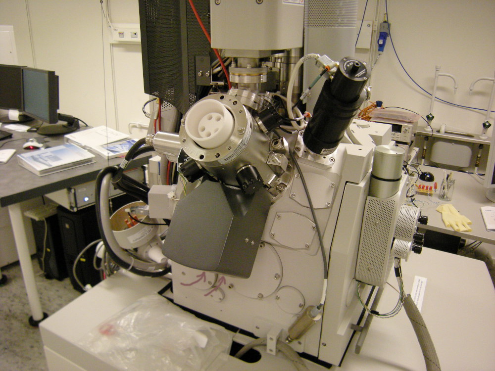
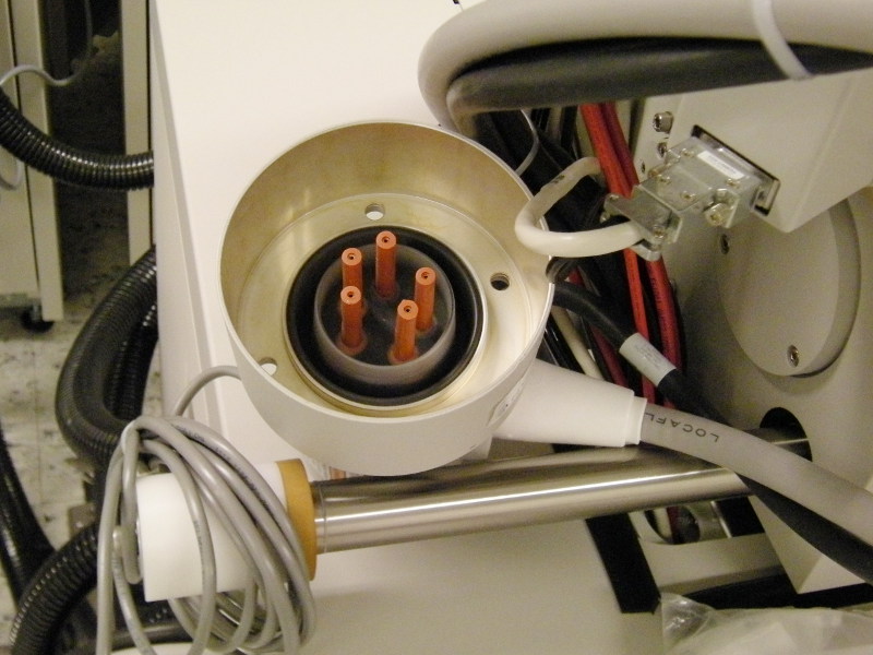
Beneath the dark grey cover mounted on the underside of the ion-column (center in pic.) there are the two small wheels for adjusting the aperture position during adjustment "210" (brown arrows).

Note the tube with co-axial connector disconnected and hanging beneath the column (bottom center).


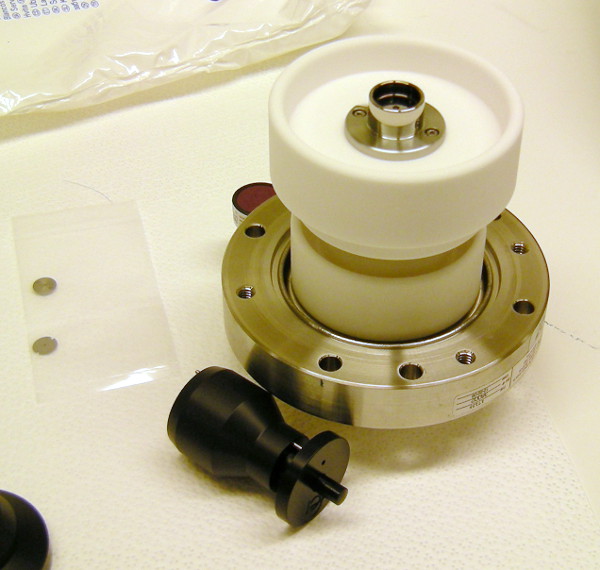
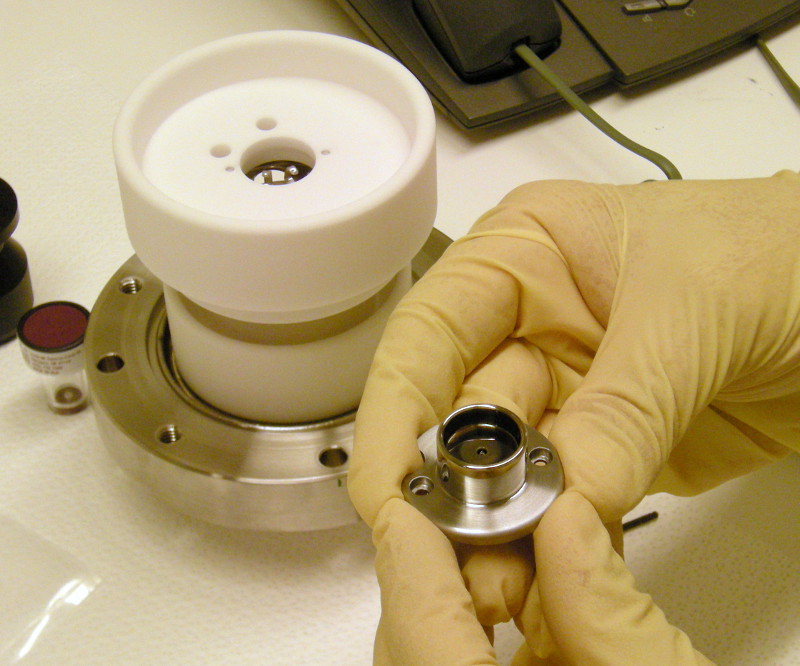
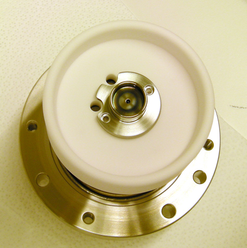
The flange with isolator and holder for the ion source is removed and placed on the work area with the ion-source holder facing upwards.


With the ion-source holder removed from the column, the BAA-holder is now visible.


The high voltage connector. The five red isolation pins are quite flexible. When re-connecting care must be taken that all five isolation pins goes into the correct (corresponding) holes in the backside of the ion-source isolator block.


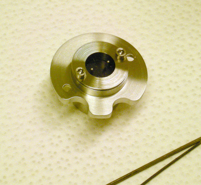
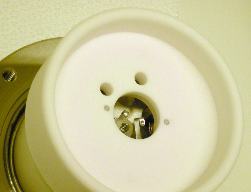
The ion source holder removed from the isolator block. Two hex-screws need to be removed for this.

Please note the cut-outs in the edge of the metal holder, corresponding to the two larger holes in the isolator block.


The ion source holder, backside facing up. The two connecting pins to the ion-source are visible in the dark center area.

Remove the two small hex screws in order to take out the old ion source.


With the metal holder for the ion source removed, the connecting tabs beneath are visible.


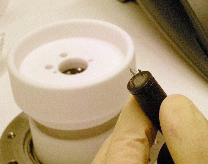
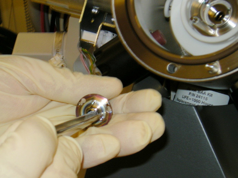
One of the special tools are used to hold the old source when extracted, and most importantly, when inserting the new source into the metal holder.

Extreme care must be taken not to touch the tip of the new source onto anything!


Here the metal holder with the new ion-source is put back into the isolator block. Note the cutouts in the periphery of the metal holder is matching the two big holes in the isolator.


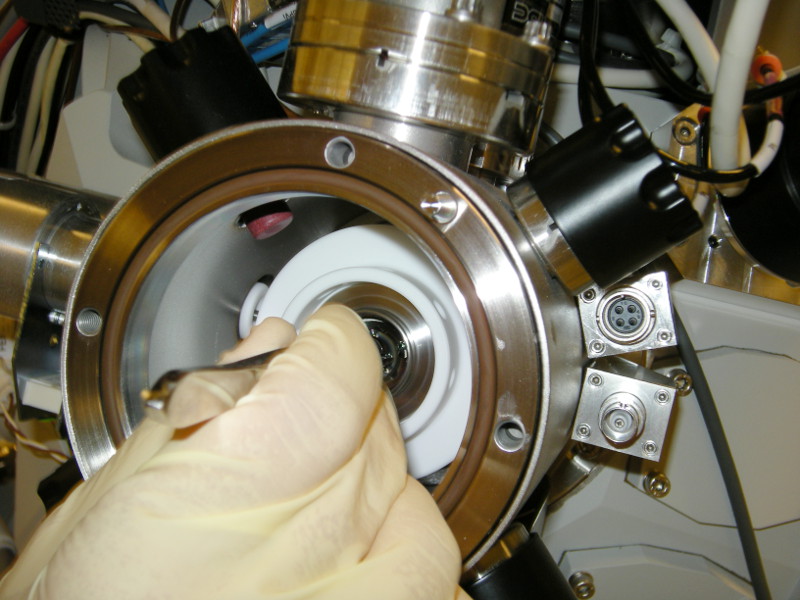
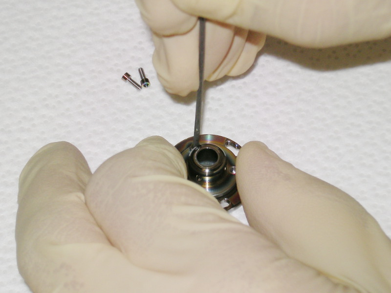
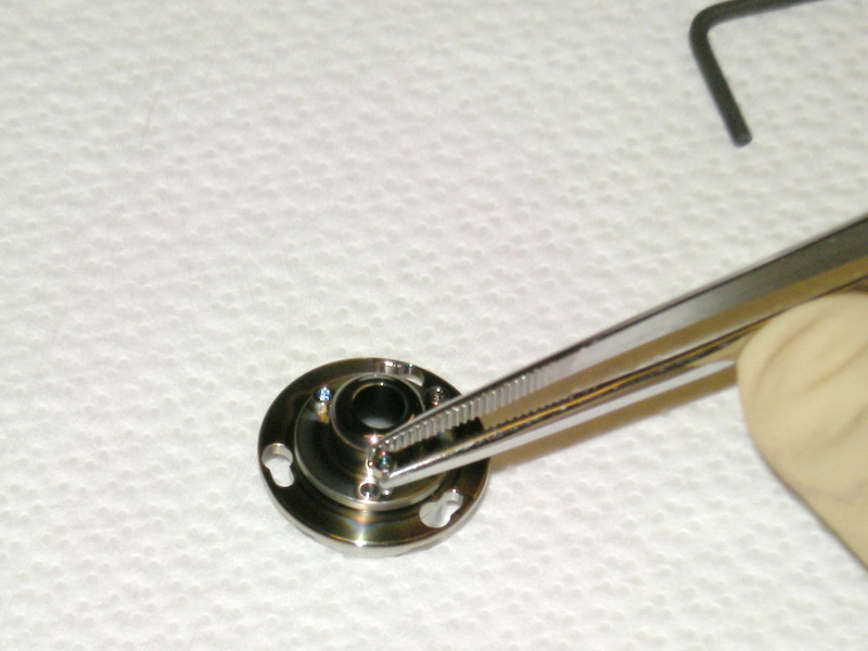
Next the BAA holder is removed, loosen three screws at the outer periphery of the holder, turn the holder and slide it over the heads of the screws, using a tweezer.


BAA holder removed.


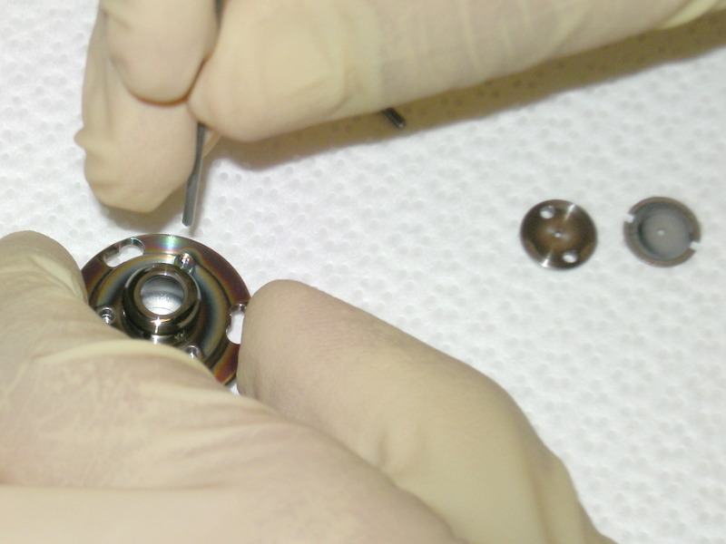
Place the BAA holder with the three inner screws facing upwards. Remove the screws to unmount the top of the holder.


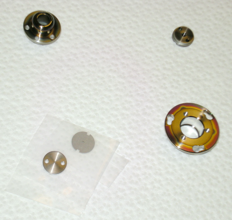
Parts of the BAA unit.
  • Top left: cover of holder
  • Top right: old gasket, should be re-used?????
  • Bottom left: new BAA and gasket????
  • Bottom right: bottom part of BAA-holder.


Mounting the top cover of the BAA-holder over the new BAA and gasket. Old BAA and gasket to the left.


Mounting the small hex-screws to fasten the top cover of the BAA-holder.


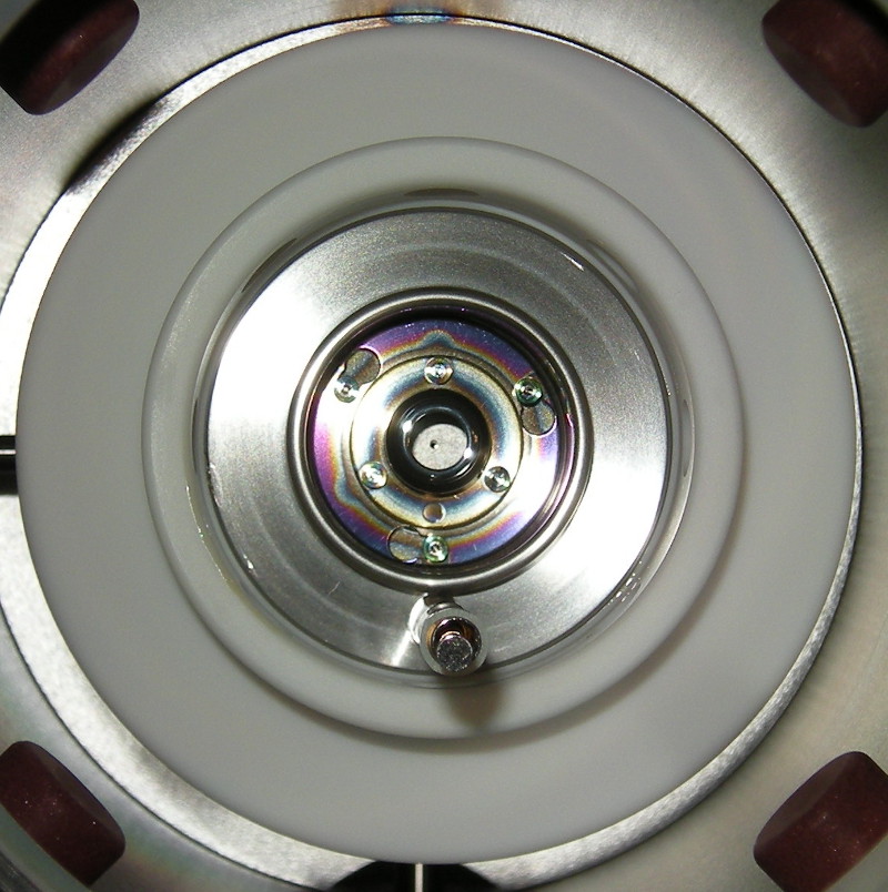
BAA-holder with new BAA mounted inside the ion-column.

The inner ends of the four black adjustment knobs can be seen in the four corners of the image. They are of reddish rubber like material that pushes on the ion-source holder to make the first coarse alignment.


Anders Liljeborg Nanostructure Physics, KTH.