|
Two micro manipulators manufactured by Kleindiek are installed
inside the FEI Nova 200 on a special extra base. Here is a brief
user manual how to use these manipulators.
Please note! Reading this web-page is not enough to be able to use these manipulators in a safe way. You MUST receive training from a person responsible for these! |
|
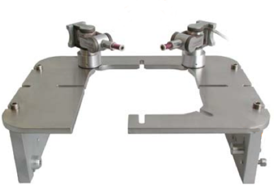
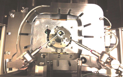
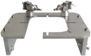
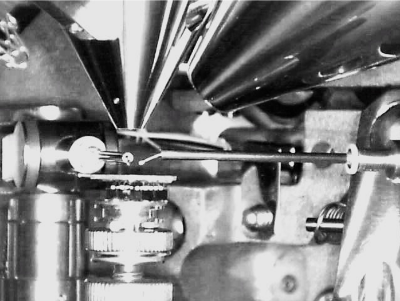
| Here are the two manipulators mounted on the special extra base-plate installed inside the FEI Nova 200. |
|
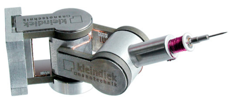
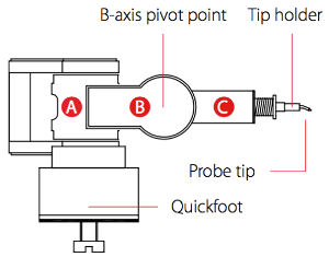
Each manipulator has three parts for each movment direction:
|
|
| This is the controller for one of the manipulators, the three first knobs control the respective motion direction. |
|
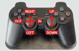
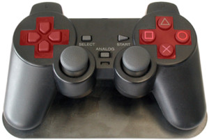
| Here is a more convenient controller (which many of you may recognise). Both manipulators can be controlled with this. The two joy sticks control the motions as indicated. |
|
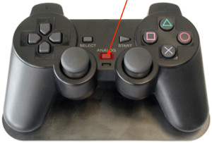
| Here is the On / Off button. |
|
|
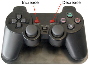
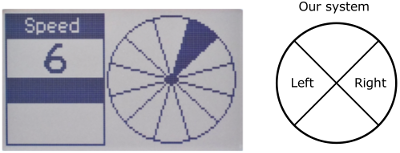
The speed of the motion is controlled by these two buttons.
Please note that the highest speed (6) can only be used when the stage is open for mounting samples etc. When the stage is inside the chamber, the risk of pushing a tip into a column, a wall, your sample, etc. is 100%. |
|
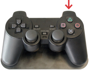
| You can switch between the two manipulators with the right front button. |
|
The driving principle is using a piezoelectric motor, a "NanoMotor" There are two modes this motor can operate in:
| |
|
| In order to take one coarse step (length of step depends on speed setting) you press one of the indicated buttons. Up / Down, Left / Right, In / Out ???? |
|
Considerations
| |
|
Speed & control settingThe speed and which manipulator is active with the controller is indicated on the display (which display??????) As we have only two manipulators installed we only have left and right.Use highest speed 6 ONLY with open load lock!
|
|
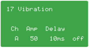
Vibration can be applied to the tip of the manipulator, this is very
useful to decide when tip makes contact with sample surface.
|
|
|
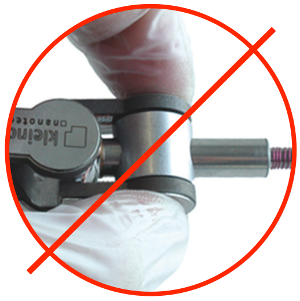
HandlingAvoid applying pressure onto forks of the horizontal and vertical axes. Pressure higher than 2 N will damage the high preceision bearings. |
|
|
Handling
|
|
|
HandlingDo not get in touch with the delicate wires.

|
|
|
Handling tips |
|
|
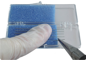
Preparing a new tip ‐ staff only |
|
|
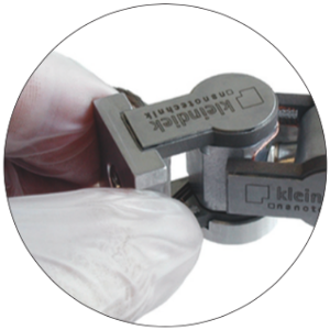
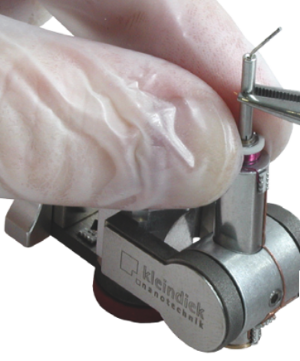
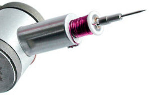
Mounting tipHold by white ring! When inserting or removing a tip holder, point the vertical axis of the manipulator directly upward and hold the manipulator firmly by the white ring at the front of the linear axis. If access from above is restricted then either move the axis as far upward as it will go or point it directly downward. Use pliers to insert or remove the tip holder.Insertion only a few mm! |
|
|
Rotator
|
|
|
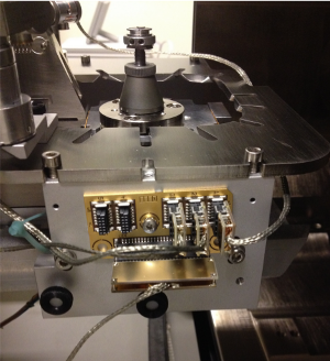
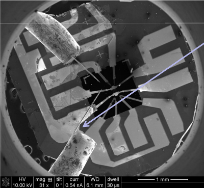
System view from aboveRotator is mounted to the right. |
|
| Manipulators are mounted on the base with friction fasteners — some adjustment possible. |
|
|
Connectors and wiresBe careful with wires when loading and unloading.Check there is enough range for tilts. |
|
|
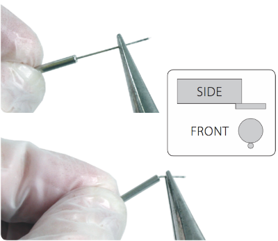
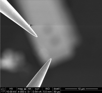
Needles / tipsSelect tip depending on purposeDo not destroy sharp tips (scratching, glue etc.) FIB your own tip
Keep within known position: Rotation: tip at rotation axis, i.e. never mount an angled tip on the rotator |
|
|
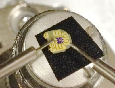
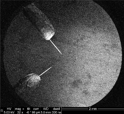
Position tips within 2 mm of centerHard to see actual tipsMay crash on:
|
|
|
CCD camera viewView from inside of chamberWatch when:
Do not squeeze manipulators into column! |
|
|
Locate needles after loadingShould be within 3 mm of stage center
If not visible:
|
|
|
Check needle rotation orientationRotator needle may touch only when on the bottom side of the wire. |
|
|
Rmember tip holder??????Rotation tricky ??????? |
|
|
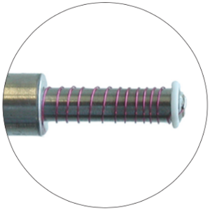
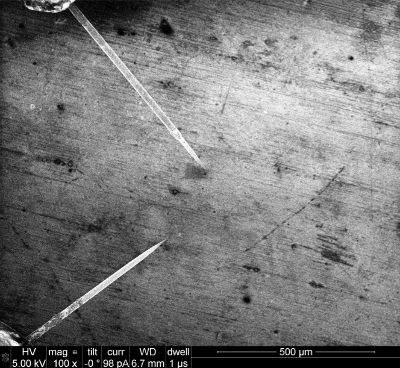
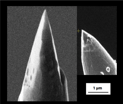
Tip shapeThis is how fresh sharp tips should look like |
|
|
Sharp tips — FIB:ed |
|
Scratching deposited layers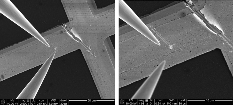
| |
|
Scratching...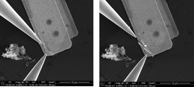
Effect depends on speed and angle | |
|
Moving small objects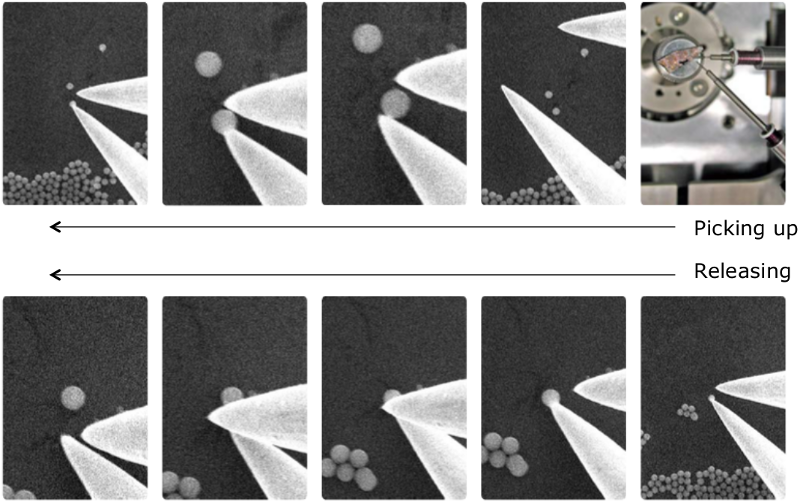
| |
|
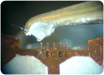
SEM-glueGlue cured by the electron beam
Manipulate:
Cure:
Wait 1 minute
Bonding strength
Fully cure:
|
|
Demo movies
http://www.nanotechnik.com/nanomanipulation.html http://www.nanotechnik.com/mm3a-em.html
| |