- Click the Select Experiment icon in the NanoScope toolbar. This opens the Select Experiment window, shown in Figure 1.
|
|
|
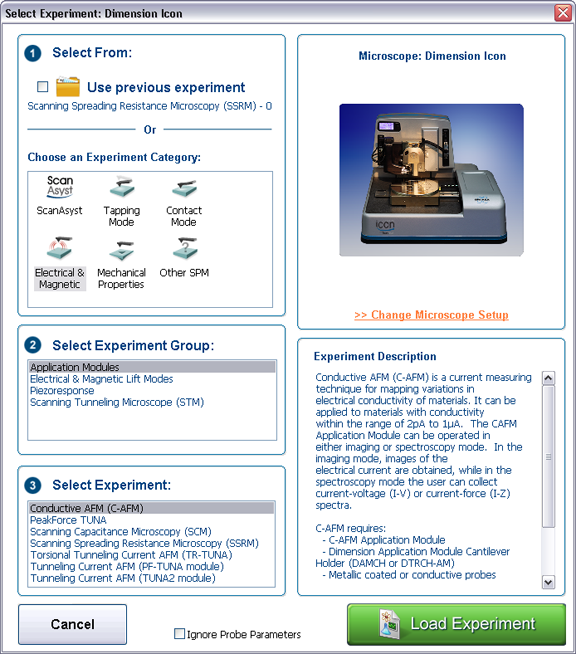
Figure 1: The Select Experiment, C-AFM mode, window.
|
|
|
|
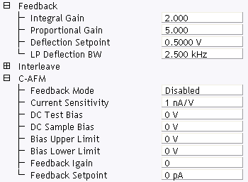
Figure 2: C-AFM control parameters in the Scan Parameter list
|
NOTE: If you have Torsional Resonance and C-AFM, there is an additional mode. Refer to TUNA and TR Mode for details.
Bruker recommends performing C-AFM measurements in open loop mode only. In open loop mode, the user selects a DC bias and measures the current passing through the sample. The Scan Parameters relevant to C-AFM are shown in Table 1. |
| Parameter | Use with C-AFM |
|---|---|
| Feedback Mode | Disabled: open loop. Enabled: closed loop. For C-AFM, select Disabled. |
| Current Sensitivity |
Selects the gain of the C-AFM sensor:
|
| DC Test Bias | Provides an additional bias for the purpose of testing the C-AFM sensor. |
| DC Sample Bias | Selectable bias to chuck/sample. |
| Bias Upper Limit | Limits the maximum bias. |
| Bias Lower Limit | Limits the minimum bias applied to the chuck/ sample in closed loop mode. |
| Feedback Igain | Integral gain used for closed-loop mode. |
| Feedback Setpoint | Not used in open loop mode. Selects the current setpoint in closed loop mode. |
Table 1: C-AFM Control parameters
Ensure that you reset the parameters to their default values (12) when using the standard air tapping or TR holder.
| www.bruker.com | Bruker Corporation |
| www.brukerafmprobes.com | 112 Robin Hill Rd. |
| nanoscaleworld.bruker-axs.com/nanoscaleworld/ | Santa Barbara, CA 93117 |
| Customer Support: (800) 873-9750 | |
| Copyright 2010, 2011. All Rights Reserved. |