NanoScope software permits “IV” measurements (current, I, as a function of voltage, V) in a specified location on the sample. Typically the SPM tip is placed at the center of an image where an IV-spectrum is captured. By applying X and Y Offsets, the tip may be moved to other locations.
|
|
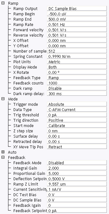
Figure 1: The Ramp Parameter list window
| Parameter | Use with C-AFM |
|---|---|
| Ramp Output |
Select a C-AFM parameter to ramp:
|
| Ramp Begin, Ramp End | The beginning and end points of a ramp. |
| Ramp Rate | All ramps are begin-end-begin cycles. Ramp Rate refers to one complete cycle. |
| Forward velocity, Reverse velocity | The ramp value from beginning to end, or end to beginning. |
| X Offset, Y Offset | Moves the probe tip to a different location. |
| Number of samples | The number of sample points per ramp (minimum 16, maximum 64,000 for low, < 0.31 Hz, Ramp Rates). |
| Plot Units | Metric or Volts |
| Feedback Type |
Ensures that the deflection feedback is ON during ramping. Settings:
|
| Feedback Counts | Select 50 for proper feedback. |
| Feedback Value | Select 0 V. |
| Dark ramp | Enable or Disable. Refer to Dark Lift for details. |
| Refer to Dark ramp delay | Time after laser is turned on. |
Table 1: C-AFM: Ramp Controls Parameters in the Ramp Parameter list window
|
NOTE: Ramp Rate, Forward Velocity and Reverse Velocity are interdependent. Changing a velocity affects the overall Ramp Rate, and vice versa.
|
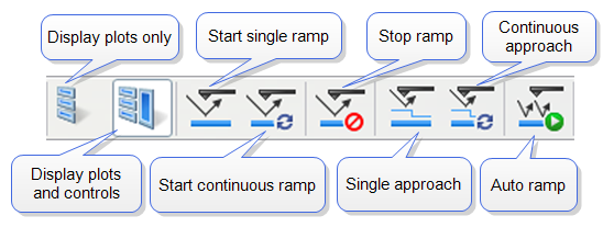
Figure 2: Toolbar Buttons: Start, Stop and Capture Ramp Curves
|
|
|
|
|
|
Trigger Mode enables limiting the current passing through a sample to protect it. See the Ramp > Mode panel (see Figure 3) for trigger parameters. describes trigger parameter functions. |
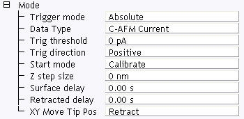
Figure 3: The C-AFM Ramp Mode panel
| Parameter | Use with C-AFM |
|---|---|
| Trigger Mode | Triggering is either Off, Absolute or Relative. For IV-spectra select Absolute to turn the trigger on (see following caution). |
| Data Type | For IV-Spectra, select C-AFM Current for triggering on the current. |
| Trigger threshold | This sets the trigger value. For a current sensitivity of 1nA/V, select any value between +10nA and –10nA. For a current sensitivity of 100nA/V, select any value between +1000nA and –1000nA. |
| Trigger direction | See Trigger Direction |
| Start mode |
Start mode allows you to switch between the various force modes without returning to image mode. Range or Settings:
|
| Z step size | The change in tip height per step when using force step. |
| Surface delay |
Specifies a delay when the tip reaches the point closest to the sample. Range or Settings:
|
| Retracted delay |
Similar to Surface delay, this value specifies the duration of the delay when the piezo is at the top of the cycle (farthest away from the sample). Range or Settings:
|
| XY Move Tip Pos |
Three options are available for moving, in XY, from one point to another:
|
Table 2: C-AFM: Mode Panel Parameters
|
Triggering requires specifying the Trigger Direction.
|
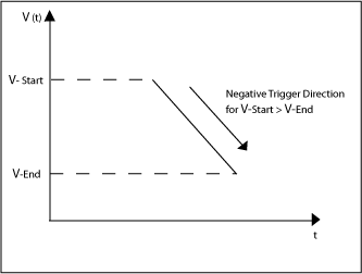
Figure 4: C-AFM: Negative Trigger Direction for VStart > VEnd
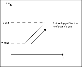
Figure 5: C-AFM: Positive Trigger Direction for VStart < VEnd
|
The Mode panel offers two more parameters that are used to independently add delay times at the end of a start-end ramp, or at the end of a complete start-end-start cycle (see Figure 6). |
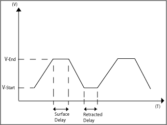
Figure 6: C-AFM: Delaying Ramps
| www.bruker.com | Bruker Corporation |
| www.brukerafmprobes.com | 112 Robin Hill Rd. |
| nanoscaleworld.bruker-axs.com/nanoscaleworld/ | Santa Barbara, CA 93117 |
| Customer Support: (800) 873-9750 | |
| Copyright 2010, 2011. All Rights Reserved. |