The second method of performing ramps of various SCM signals uses the Ramp menu. A typical application is the measurement of dC/dV–V spectra.
|
|
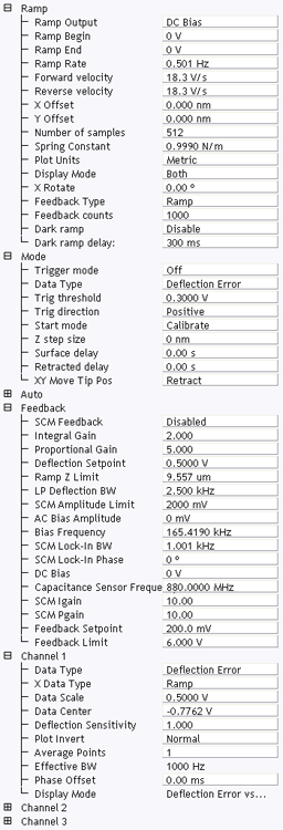
Figure 1: The Ramp Parameter list window
| Parameter | Use with SCM |
|---|---|
| Ramp Output |
Select an SCM parameter to ramp:
|
| Ramp Begin, Ramp End | The beginning and end points of a ramp. |
| Ramp Rate | All ramps are begin-end-begin cycles. Ramp Rate refers to one complete cycle. |
| Forward Velocity, Reverse Velocity | The ramp value from beginning to end, or end to beginning. |
| X Offset, Y Offset | Moves the probe tip to a different location. |
| Number of samples | The number of sample points per ramp (minimum 16, maximum 64,000 for low, < 0.31 Hz, Ramp Rates). |
| Plot Units | Metric or Volts |
| Feedback Type |
Ensures that the deflection feedback is ON during ramping. Settings:
|
| Feedback Counts | Select 50 for proper feedback. |
| Feedback Value | Select 0 V. |
| Dark ramp | Enable or Disable. Refer to Dark Lift for details. |
| Refer to Dark ramp delay | Time after laser is turned on. |
Table 1: SCM: Ramp Controls Parameters in the Ramp Parameter List Window
|
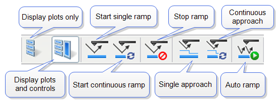
Figure 2: Toolbar Buttons: Start, Stop and Capture Ramp Curves
|
| www.bruker.com | Bruker Corporation |
| www.brukerafmprobes.com | 112 Robin Hill Rd. |
| nanoscaleworld.bruker-axs.com/nanoscaleworld/ | Santa Barbara, CA 93117 |
| Customer Support: (800) 873-9750 | |
| Copyright 2010, 2011. All Rights Reserved. |