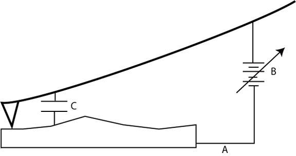
TUNA can be operated in both open and closed loop modes. However, due to the strong capacitance between the tip and sample (see (C) in Figure 1), closed loop TUNA measurements may not yield the desired results.
Figure 1: Feedback Loop in Closed Loop Mode
The tip-sample capacitance is on the order of a few pF and yields a current (I).

where:
As the voltage changes rapidly (due to the feedback loop), it is possible for the feedback current (see (A), Figure 1) to become greater than the current being measured. Therefore, lower gain settings (e.g.,1 nA/V and 100 nA/V) are recommended when operating in closed loop mode.
Prior to engaging in closed loop mode, follow the procedure in Open Loop TUNA Imaging. Be sure to adhere to the control parameters set forth in Table 1 in Software Selection. After finishing the procedure and while still in open loop mode, complete the following:
In the appropriate channel, set the Data Type to Feedback Bias to view the applied bias.
In the appropriate channel, set Real-Time Plane Fit and Offline Plane Fit to None.
The feedback current and bias limits will depend upon the sample being imaged and the gain settings for the TUNA sensor.
| www.bruker.com | Bruker Corporation |
| www.brukerafmprobes.com | 112 Robin Hill Rd. |
| nanoscaleworld.bruker-axs.com/nanoscaleworld/ | Santa Barbara, CA 93117 |
| Customer Support: (800) 873-9750 | |
| Copyright 2010, 2011. All Rights Reserved. |