- Click the Select Experiment icon in the NanoScope toolbar. This opens the Select Experiment window, shown in Figure 1.
|
|
|
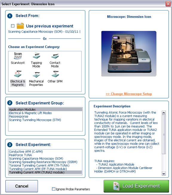
Figure 1: The Select Experiment, TUNA mode, window.
|
|
|
|
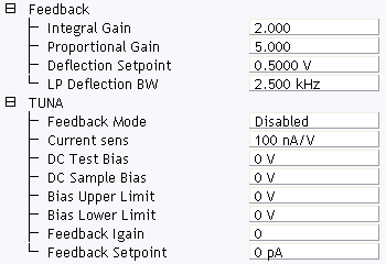
Figure 2: TUNA control parameters in the Scan Parameter list
|
NOTE: If you have PeakForce Qnm and TUNA, there is an additional mode PeakForce TUNA.
NOTE: If you have Torsional Resonance and TUNA, there is an additional mode. Refer to TUNA and TR Mode for details.
Bruker recommends performing TUNA measurements in open loop mode only. (For information about TUNA measurements in closed loop mode, refer to Closed Loop TUNA Imaging). Select a DC bias and measure the current passing through the sample. The Scan Parameters relevant to TUNA are shown in Table 1. |
| Parameter | Use with TUNA |
|---|---|
| Feedback Mode | Disabled: open loop. Enabled: closed loop. For TUNA, select Disabled. |
| Current sens |
Selects the gain of the TUNA sensor:
|
| DC Test Bias | Provides an additional bias for the purpose of testing the TUNA sensor. |
| DC Sample Bias | Selectable bias to chuck/sample. |
| Bias Upper Limit | Limits the maximum bias applied to the chuck/ sample in closed loop mode. |
| Bias Lower Limit | Limits the minimum bias applied to the chuck/ sample in closed loop mode. |
| Feedback Igain | Integral gain used for closed-loop mode. |
| Feedback Setpoint | Not used in open loop mode. Selects the current setpoint in closed loop mode. |
Table 1: TUNA Control parameters
Ensure that you reset the parameters to their default values (12) when using the standard air tapping or TR holder.
| www.bruker.com | Bruker Corporation |
| www.brukerafmprobes.com | 112 Robin Hill Rd. |
| nanoscaleworld.bruker-axs.com/nanoscaleworld/ | Santa Barbara, CA 93117 |
| Customer Support: (800) 873-9750 | |
| Copyright 2010, 2011. All Rights Reserved. |