EC Sample Base and Software Setup
| |
- Start the NanoScope software and enter Realtime.
- From the menu bar, select Stage > Initialize... to initialize the Dimension Icon stage.
- After the stage has initialized, locate the probe tip using the Locate Tip command.
- Using the camera/optics, find the alignment mark in the center of the heater cover:
|

|
- Click the Navigate icon in the Workflow Toolbar. This activates the Navigate view, shown in Figure 1.
|
| |
- Use the trackball or the XY Stage Control buttons in the Navigate window to center the alignment mark.
|
| |
|
| |
|
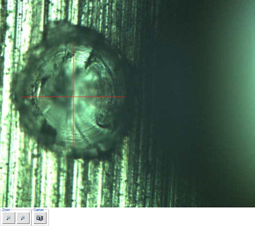
Figure 1: The Navigate Window showing the alignment mark in the sample base
| |
NOTE: Ensure that the head is raised high enough not to hit the EC cell when moving the XY stage.
|
| |
- Click 2.2 Teach Blind Engage Position, shown in Figure 2.
|
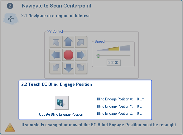
Figure 2: Click 2.2 Teach Blind Engage Position
| |
NOTE: When the using the EC cell, only ± 2470 μm (7000 μm circular, ± 5000 μm for the Electrochemistry Cell) of XY stage motion is possible. If you move more than that when the microscope is focused on the EC sample, your microscope may hit the inside of the EC cell.
|
| |
CAUTION: When moving the XY stage when the AFM microscope is focused on the EC sample, ensure that these coordinates are never greater than ± 2470 μm.
|
| |
- Click 3.1 Move to Add Fluid Position, shown in Figure 3, to move the EC cell away from the head.
|
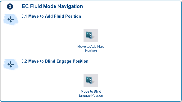
Figure 3: Click 3.1 Move to Add Fluid Position
| |
- Add fluid to the EC Cell
|
| |
NOTE: The Dimension General Purpose Electrochemistry Cell has a capacity of 2.5 ml of fluid. Do not overfill the EC cell or damage to the heater in the EC chuck may result. Ensure that the fluid level is sufficiently high so that it touches the bottom window of the probe holder.
|
| |
- Click 3.1 Move to Blind Engage Position, shown in Figure 3, to move the EC cell under the head.
|

|
- Click the Setup icon in the Workflow toolbar. This activates the Setup view shown inFigure 4.
|
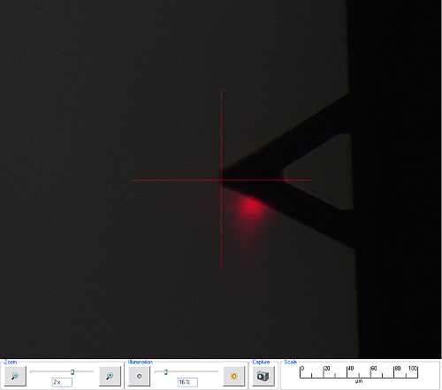
Figure 4: Desired laser position (cross-hairs) in the Setup view
| |
- Click where the laser should be in the video window. See Figure 4.
- Move the laser to this position. See Figure 5.
|
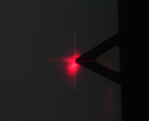
Figure 5: Laser moved to cursor position.
| |
- Use the focus controls to focus the optics on the cantilever. See Figure 6.
|
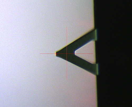
Figure 6: Focus the optics on the cantilever.

|
- Engage
|
Return to Setup Procedures.
| www.bruker.com
|
Bruker Corporation |
| www.brukerafmprobes.com
|
112 Robin Hill Rd. |
| nanoscaleworld.bruker-axs.com/nanoscaleworld/
|
Santa Barbara, CA 93117 |
| |
|
| |
Customer Support: (800) 873-9750 |
| |
Copyright 2010, 2011. All Rights Reserved. |
Open topic with navigation