LakeShore 331S Front Panel Control
Front Panel Displays
The temperature controller is pre-programmed with default settings (see Default Temperature Controller Settings) that influence the liquid crystal display (LCD) readings. The default settings are appropriate for standard use of the temperature controller with the Dimension Icon Electrochemical Cell; no modifications are needed.
The symbols displayed by the LCD are:
- A: Sensor input A
- B: sensor input B
- S: Setpoint
- V: Sensor units (volts)
- ¾: Sensor units (ohms)
- mV: Sensor units (millivolts)
- K: Temperature in Kelvin
- C: Temperature, Celsius
- >: Maximum value
- <: Minimum value
- /: Linear equation result
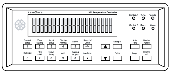
Figure 1: Front of LakeShore 331 Temperature Controller
Typically, after initial power-up, the LCD is treated as four equal-sized subpanels (see Figure 1). To change what is displayed in one of the subpanels:
- Press the Display Format button (under the LCD, top row, button “4”). “Display Location 1” appears written in the lower half of the LCD.
- Use the up/down arrow buttons to pick among:
- Display Location 1 (upper left LCD subpanel),
- Display Location 2 (upper right LCD subpanel),
- Location 3 (lower left), etc.
Press Enter.
- Use the up/down arrow buttons to pick among:
- Input A
- Input B
- None
- Additional option of Setpoint for display location 3 and Heater out for display location 4.
Press Enter.
- Use the up/down arrow buttons to pick a source among:
- Temp K
- Temp C
- Sensor
- Linear
- Min
- Max
Press Enter.
NOTE: If Setpoint is entered for display location 3, only the first three source options are available. If Heater out is entered for display location 4, there are no additional options to enter.
The six front panel light emitting diode (LED) “annunciators” record system status in normal operation. In normal operation, only the first light, Control A, is on.
- Control A (B): On when Input A (B) is the control input.
- Tune: On continuously when Auto Tune is on, and blinks when Auto Tune is actively gathering data.
- Ramp: On continuously when the Ramp feature is on, and blinks during a setpoint ramp.
- Remote: On when in Remote Mode (i.e., controlled through the IEEE-488 interface or RS-232 port).
NOTE: The IEEE-488 interface is not necessary for normal Dimension Icon Electrochemistry Cell function.
- Alarm: On continuously when the alarm feature is on, and blinks when any alarm is activated.
NOTE: Alarms have not been programmed as a part of Dimension Icon Electrochemistry Cell function, but can be used if desired.
Basic Front Panel Operation
The full set of front panel functions is listed below. However, only a few of the front panel buttons are regularly used:
To enter a temperature setpoint:
- Press Setpoint.
- Enter a number (via the numbered dual function buttons in the left half of the front panel buttons).
- Press Enter.
To turn on the heater:
- Press Heater range.
- Toggle the arrow buttons to select High.
- Press Enter.
To turn off the heater:
NOTE: These basic functions can also be controlled with the NanoScope software.
Front Panel Button Functions
There are 20 front panel function buttons (see Figure 1). Here they are listed from top-to-bottom and left-to-right and described briefly. See Default Temperature Controller Settings for the default values given to these parameters initially, and refer to the LakeShore 331 User’s Manual for more detail about each function.
- Control Setup: Selects control input, setpoint units, closed vs. open loop control mode, power up enable, setpoint ramp enable, ramp rate, and display of heater output units.
- Setpoint: The target setting of the active control loop.
- Zone Setting: provides for entry of ≤10 temperature control zones, each with its own PID (see next) control parameter settings.
- PID/MHP: Permits manual adjustment of control parameters Proportional (P), Integral (I) and Derivative (D), or Manual Heater Power (MHP) for the control loop.
- Input Setup: Selects among sensor types and associated temperature calibration curves.
- Curve Entry: Allows entry of up to twenty 200-point custom temperature calibration curves.
- Display Format: Enables programming the LCD.
- Math: Configures features Max/Min, linear equation and filter. Press twice to restore the default Max/Min settings.
- Alarm: Used to enable alarms and relays.
- Analog Output: Configures the analog output feature.
- Remote/Local: Selects between the IEEE-488 interface and local operation of the controller.
- Interface: Sets the baud rate of the serial interface and sets IEEE-488 address an terminators.
- Up arrow key: For parameter selection and incrementing numbers.
- Down arrow key: For parameter selection and decrementing numbers.
- Escape: Terminates a setting function without changing parameter values.
- Enter: Completes setting functions and returns to normal operation.
- Auto Tune: Selects among tuning modes: AutoTune PID, PI, P, Manual PID or Zone for the control loop.
- Loop: Toggles between control loop 1 and 2.
NOTE: The Dimension Icon Electrochemistry Cell employs control loop 1 exclusively.
- Heater Range: Selects among High, Med(ium) and Low.
- Heater Off: Turns the heater off.
- 0–9, +/-: Used for numeric entries.
| www.bruker.com
|
Bruker Corporation |
| www.brukerafmprobes.com
|
112 Robin Hill Rd. |
| nanoscaleworld.bruker-axs.com/nanoscaleworld/
|
Santa Barbara, CA 93117 |
| |
|
| |
Customer Support: (800) 873-9750 |
| |
Copyright 2010, 2011. All Rights Reserved. |
Open topic with navigation