Prior to imaging samples at non-ambient temperatures, inspect the cooling lines for air bubbles. Bubbles can destabilize temperature control of the sample. A few minutes of pumping prior to heating is sufficient to eliminate bubbles from the coolant. This is always advisable after the system has been off for several hours. Verify that fluid flows at the output of the reservoir.
In a typical experiment, a sample is examined at room temperature before its temperature is changed to a target value.
CAUTION: Disengage the probe from the sample prior to heating to avoid unwanted contact as the sample and heater components expand with temperature. Only small (5–10°C) temperature increases can be performed safely without tip withdrawal. By the same logic, large (> 30°C) temperature rises require further removal of the probe tip from the sample.
Measurements at temperatures up to 75°C can be performed without powering the probe heater. However, when operating at higher temperatures, it is advised to use the Tip Heater to avoid condensation of moisture or the deposition of volatile sample components on the cantilever. These contaminants can destabilize the cantilever resonance and reduce the optical reflectivity to the laser beam.
Stable imaging in TappingMode is the main purpose of the Tip Heater. Due to difficulties in measuring probe temperature, its heating is regulated by a voltage applied to the heater, which is installed in direct contact with the probe substrate. An increase of 1 volt raises substrate temperature approximately 10°C. It has been demonstrated that the application of ≤ 7 V is sufficient for stable imaging in the range of 75–140°C. The applied voltage needed gradually increases for imaging at higher temperatures. However, long-term operation at voltages above 15 V may diminish the life of the piezostack-activated probe tapping oscillator.
The heated TappingMode (air) probe holder in combination with the silicone rubber seal provides the option to control the atmosphere around the heated sample by purging with inert, dry, non-corrosive gases (e.g., nitrogen, argon, helium, etc).
Because of the possibility for material oxidation at high temperature, the gas-tight heater/sample chamber can be purged of oxygen with an inert gas (e.g. nitrogen, argon, helium, etc.). The small volume of the sample enclosure allows purging to be accomplished in 1–3 minutes at a rate of 5–10 ml/min. Gas replacement verification is easily checked using helium as a substitute for air because the resonant frequency of the cantilever in helium is slightly raised, while its quality factor increases markedly.
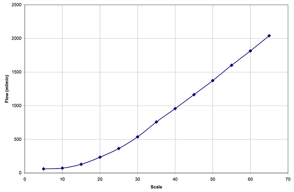
The flow meter calibration curve, shown in Figure 1, shows flow rate, in ml/min vs. the scale markings on the flow meter.
Figure 1: Flow meter calibration curve
Purging the sample chamber with inert gas leads to an increase in heat consumption and thus can reduce the maximum attainable sample temperature or increase the minimum attainable sample temperature.
Dry nitrogen gas purging, at 50–500 ml/min, may not be required for sub-ambient operation in air, but is required for temperatures near and below 0°C. Flow rates less than 50 ml/min. are generally too low to prevent ice formation, while flow rates greater than
Room temperature water, with the coolant reservoir, is sufficient for heating and for cooling to approximately –20°C.
Reaching the lowest specified operating temperature requires the use of ice water as the coolant directly from the ice bucket. Remove the silicone tubes from the reservoir and insert them into the ice water bucket. Reaching the lowest specified operating temperature also requires use of no sample puck or the smallest sample puck (6 mm).
Each time the pump system is started the user should inspect for leaks, particularly near the base of the scanner. Periodically monitor the cooling system for leaks during operation and replace leaky tubing.
When the pump is first started, the pulse damper (see Cooling System) will take a few minutes to fill before cooling water starts to flow back into the reservoir. Furthermore, coolant flow will not stop immediately when the pump is turned off because the coolant inside the pulse damper will continue to flow for several minutes.
Because the
The Heater/Cooler element should not be enabled until the cooling system is completely filled.
Bruker sets the heater and temperature sensors, which do not normally require recalibration. The temperature measured and controlled by the heater controller is that of the heating/cooling element, not the sample. For the most accurate sample temperature measurement, measure the sample temperature independently using an optional temperature sensor.
| www.bruker.com | Bruker Corporation |
| www.brukerafmprobes.com | 112 Robin Hill Rd. |
| nanoscaleworld.bruker-axs.com/nanoscaleworld/ | Santa Barbara, CA 93117 |
| Customer Support: (800) 873-9750 | |
| Copyright 2010, 2011. All Rights Reserved. |