If you have a NanoScope V Controller and NanoScope 7.30 or later software, the Thermal Applications Controller can be controlled using the NanoScope software, as described below. Earlier NanoScope or NanoDrive software requires front panel control, discussed in TAC Panel Control.
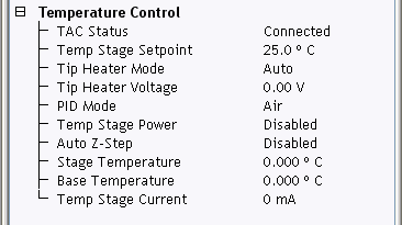
Sample and tip heater temperatures can be controlled through the Temperature Control panel, available in either the Scan view:
Z-drift can be a significant problem for heating (and cooling) due to thermal expansion. The purpose of the Auto Z-Step function is to keep the Z-center position from becoming extended or retracted, as a result of z-drift.
To activate Auto Z-Step:
With Auto Z-Step enabled in the Temperature Control panel and started via the window, NanoScope software automatically steps the z-stage up or down whenever the z-center voltage drifts too far towards the fully retracted or fully extended position. These two z-positions are user defined by Retracted Threshold and Extended Threshold, shown in Figure 1. When the z-center voltage is less than Retracted Threshold, then the z-stage is stepped "up" (by the Motor Step Size) until the z-center is at the Target Z-Center.
The Withdraw Threshold, for the retracted side only, protects against feedback errors, which cause the Z piezo to fully retract. If the Z-center is less than the Retracted Threshold, the probe is automatically withdrawn.
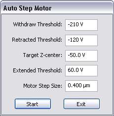
Figure 1: Auto Step Motor window
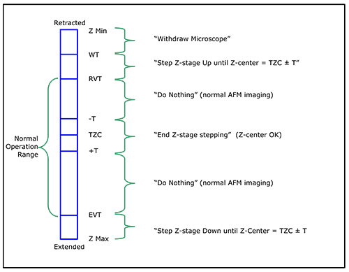
Auto Z-Step logic is shown in Figure 2 with the Auto Step Motor functions and symbols defined below.
| Parameter | Settings |
|---|---|
|
Retracted Voltage Threshold (RVT) |
|
|
Extended Voltage Threshold (EVT) |
|
|
Target Z-Center (TZC) |
|
|
Withdraw Threshold (WT) |
|
|
Motor Step Size |
|
|
Start |
|
|
Stop |
|
|
Exit |
|
|
Target ± tolerance (T) |
|
Table 1: Parameters and Setting Ranges and Defaults for the Auto Step Motor Window
The purpose of the short withdraw function is to provide you with a safe means to change temperature, adjust the detector and feedback settings, tune the cantilever tune, etc. in close proximity to the surface so that the temperature of the tip and sample remain stable and the gas seal is maintained.
The Short Withdraw function is available only when the tip is engaged on the sample surface. To execute a Short Withdraw, select Microscope > Short Withdraw from the NanoScope menu.
To change the short withdraw distance (the factory default is 20 μm):
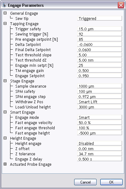
Figure 3: Engage Parameters window
Due to the additional mass of the Heater/Cooler TappingMode Probe Holder, some systems may oscillate following engage. In this situation, the software will automatically reset the x and y integral gain values to protect the scanner. An error log dialog window will appear to inform the user. See Closed Loop XY Calibration for more information.
| www.bruker.com | Bruker Corporation |
| www.brukerafmprobes.com | 112 Robin Hill Rd. |
| nanoscaleworld.bruker-axs.com/nanoscaleworld/ | Santa Barbara, CA 93117 |
| Customer Support: (800) 873-9750 | |
| Copyright 2010, 2011. All Rights Reserved. |