- Mount a sample onto the sample holder.
- Mount an appropriate probe into the standard probe holder (see Prepare and Load the Cantilever Holder for details).
- Click the Select Experiment icon to open the Select Experiment window, shown in Figure 1.
PeakForce-KPFM-AM is a is a two-pass procedure where the surface topography and nanomechanical properties are obtained using Bruker's proprietary Peak Force Tapping Mode in the first pass and the surface potential or work function in the second pass using the Lift Mode Surface Potential Imaging (AM-KPFM) mode:
PeakForce KPFM-AM leverages the advantages of PeakForce Tapping:
Bruker recommends PFQNE-AL probes for PeakForce KPFM measurements.
Prepare the sample as described in Electrical Sample Preparation.
|
|
|
|
|
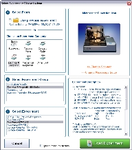
(Hover over the image to view larger)
Figure 1: The PeakForce-KPFM Select Experiment window
|
|
|
|
|
|
|
|
|

Figure 2: Align the laser on the cantilever and place the crosshair there.
|

Figure 3: The HSDC window, indicating that a cantilever tune operation is underway.
|
|
|
|
|
|
NOTE: The stored data is unaffected by the Potential Offset. I.e. offline measurements do not see this input.
|
Automatic frequency selection is the default for PeakForce KPFM imaging. You may wish, however, to manually select an operating frequency. To do this:
|
|
|
|
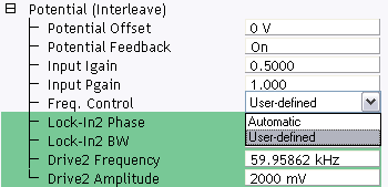
Figure 4: Selecting User-defined Frequency Control
|
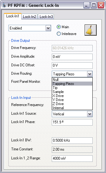
Figure 5: The PeakForce KPFM Generic Lock-In window
|
|
|
|
|
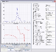
(Hover over the image to view larger)
Figure 6: The Generic Sweep window
|
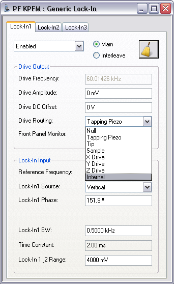
Figure 7: Set the Drive Routing to Internal
|
| www.bruker.com | Bruker Corporation |
| www.brukerafmprobes.com | 112 Robin Hill Rd. |
| nanoscaleworld.bruker-axs.com/nanoscaleworld/ | Santa Barbara, CA 93117 |
| Customer Support: (800) 873-9750 | |
| Copyright 2010, 2011. All Rights Reserved. |