Z Sensor Linearity Correction
The necessity of calibrating the Z sensor linearity varies depending on the microscope head. Certain head types will be more likely than others to require linearity correction. If you feel the Z sensor requires linearity correction, perform the procedure below.
The Z Sensor Linearity Calibration Window
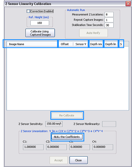
QUICK LINK: Click on the components of the window above to view a description of their function.
Procedure
NOTE: This calibration procedure is extremely sensitive to contamination, alignment, and tracking. Debris on the sample surface, poor centering of the pit, or poor tracking can cause or worsen linearity problems.
- Set up your system for TappingMode AFM operation in XY .
- Engage on a 10 μm pitch calibration standard with a scan size of 11 μm.
- Ensure that you have a pit well centered in the scan.
NOTE: Do not center a high point (line) in the scan window. The lowest point of the scan must be in the middle.
- In the Scan Parameters List, set the Aspect Ratio to 8 (this will enable the system to capture enough data to perform the calibration but save time over capturing a larger region) and set the Z Range to the maximum value (by typing 9999 into the field it will reset to the maximum limit).
- Modify the as necessary to ensure good tracking of the sample surface.
- Set the Channel 1 Data Type to Height Sensor and the Online and Offline Plane Fit to None.
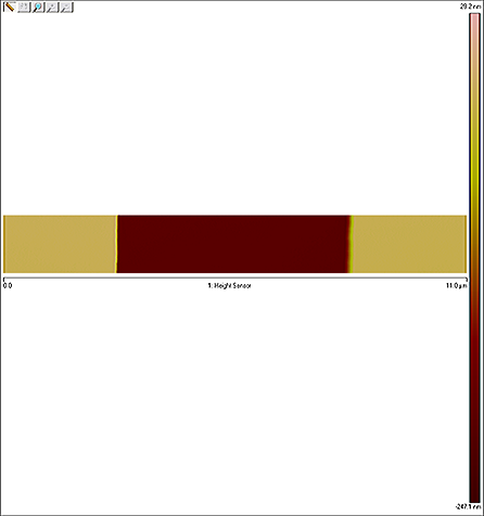
Your data should now look like the image below:
- Select Calibrate > Z Sensor Linearize from the NanoScope toolbar to open the Z Sensor Linearity Calibration window.
- In the Ref. Height (nm) box, enter the height of the calibration standard that will be scanned for calibration (generally, you will use a 180 nm calibration standard).
- Enter the number of Measurement Z Locations that will be used (10 is recommended).
- Ensure the Correction Enabled check box is deselected.
- Click the Auto Calibrate button. The system will perform scans at different extensions of the Z piezo using the Z stepper motor. After the specified number of scans (given in step 7), the software will filter the images to determine the depth of the pit in each. This data is used to compute the polynomial fit coefficients from the series of pit depths at different offsets.
- If you wish to use previously captured images, first click Calibrate Using Captured Images to load the image files you will use for calibration.
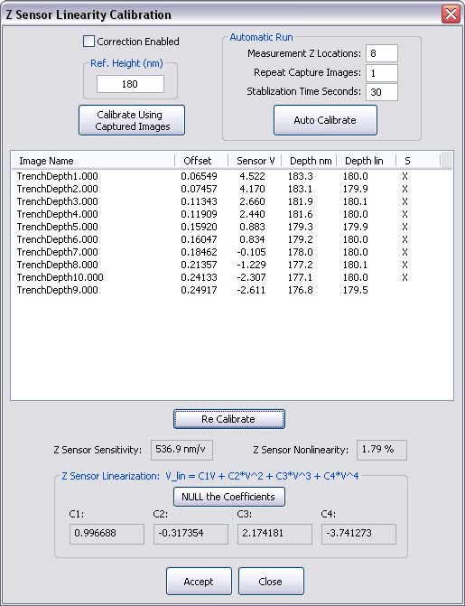
NOTE: You can remove outliers by clicking on the X in the "S" column then clicking the Re-Calibrate button to redo the calculation without that data point. In the example above, the TrenchDepth9.000 file has been removed from the analysis.
- Click Accept to begin using these coefficients and save them to the scanner file.
To verify the Z sensor linearity calibration (this is not a necessary step):
- Ensure that you are engaged and scanning the pit as in steps 1 through 4, above.
- Select Calibrate > Z Sensor Linearize to open the Z sensor linearity calibration window.
- Select the Correction Enabled check box.
- Click the Auto Verify button. As with Auto Calibration, the system will perform scans at different extensions of the Z piezo using the Z stepper motor. After the specified number of scans, the software will filter the images to determine the depth of the pit in each. This data is used to compute the polynomial fit coefficients from the series of pit depths at different offsets.:
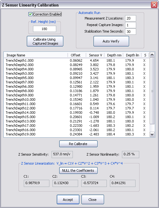
- Confirm that the Z sensor nonlinearity is within acceptable bounds.
| www.bruker.com
|
Bruker Corporation |
| www.brukerafmprobes.com
|
112 Robin Hill Rd. |
| nanoscaleworld.bruker-axs.com/nanoscaleworld/
|
Santa Barbara, CA 93117 |
| |
|
| |
Customer Support: (800) 873-9750 |
| |
Copyright 2010, 2011. All Rights Reserved. |
Open topic with navigation
 .
.