You are here: Installation and Maintenance Guide > Installation > Switching Dimension Icon and Dimension FastScan SPM Scanners > Removing the Dimension FastScan Scanner and Installing the Dimension Icon Scanner

Removing the Dimension FastScan Scanner and Installing the Dimension Icon Scanner

Users with both the Dimension Icon and Dimension FastScan scanners can select the scanner most appropriate for their investigations. It is important that the software recognize which scanner is installed. To switch from the Dimension FastScan to Dimension Icon scanner, use the procedure below.

HINT: Enter Realtime (by loading an experiment) prior to beginning the scanner swap procedure. Use the System Status Indicator to ensure the system is in order before proceeding.
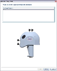
  1. Click the Select Experiment icon to open the Select Experiment window:

 
  1. Click the Change Scanner link to activate the Equipment Change wizard.
  2. Select Icon to indicate to the software which new hardware you will install:

(Hover over the image to view larger)

 
  1. Click Next. The wizard will open a window instructing you to move the stage to a safe location:

(Hover over the image to view larger)

  1. Click the Move Stage button to send the stage to a safe location.
NOTE: The Next button will not be activated until you move the stage to a safe position using the Move Stage button.
NOTE: You may not see this screen if the stage is already in the safe position.
 
  1. Click Next. The system will disable the high voltage to the scanner head. The wizard will display a window with instructions on removing the Z scanner and a diagram to help you identify the relevant components:

(Hover over the image to view larger)


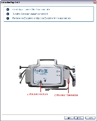
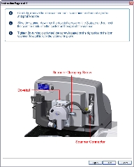
To remove the Z scanner:

  1. Using your right hand, unplug the Z scanner connector cable from the side of the Dimension FastScan scanner head.
  2. Using your left hand, grasp the Z scanner; try not to touch the bottom surface of the Z scanner, where the probe is mounted.
  3. Turn the vacuum for the Z scanner/probe holder off:
  4. Pull the Z scanner down and free of the XY scan head.
  1. Click Next. The wizard will display a window with instructions for removing the Dimension FastScan XY scan head and a diagram to help you identify the relevant components:

(Hover over the image to view larger)


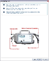
To remove the Dimension FastScan scanner:

  1. Unplug the connectors on both sides of the Dimension FastScan scanner, including the vacuum hose.
  2. Using a 3/16" hex driver, unscrew the clamp holding the Dimension FastScan scanner in the dovetail mount.
  3. Using the handles at the top and left hand side of the Dimension FastScan scanner, carefully lift it upwards and out of the dovetail.
  4. Place the Dimension FastScan scanner in the box it shipped in or on a level surface free of clutter.
CAUTION: The Z scanner apparatus is expensive and fragile. NEVER place the Dimension FastScan scanner down in such a way that the Z scanner comes into contact with the table. Lower the Dimension FastScan scanner onto the table with the labeled front piece facing upward.
  1. Click Next. The wizard will display a window with instructions for installing the Dimension Icon optics assembly and a diagram to help you identify the relevant components:

(Hover over the image to view larger)


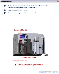
To connect the optics assembly:

  1. Gently slide the Dimension Icon optics onto the left-side dovetail; push them all the way to the right until they come to a hard stop.
  2. Tightening the clamping screw with the 3/16" hex driver.
CAUTION: Be very careful to adjust only the optics clamping screw. It is the middle of 3 screws located on the optics assembly. Turning the other screws could move the system optics out of alignment.
  1. Plug in the optics cables.
  1. Click Next. The wizard will display a window with instructions for installing the Dimension Icon scanner and a diagram to help you identify the relevant components:

(Hover over the image to view larger)


To connect the Dimension Icon scanner:

  1. Carefully remove the Dimension Icon scanner from its container and slide it down into the dovetail groove of the Z-stage.
  2. When sliding the Dimension Icon scanner into the dovetail, make sure that the probe tip will not touch the sample. If it appears that the tip may touch when the scanner is fully inserted in the dovetail, raise the Z-stage by selecting Microscope > Withdraw several times, or by selecting Navigate > Focus Surface and raising the Z-stage upward.
  3. Tighten (by turning counterclockwise) the screw located on the right side of the Dimension Icon scanner dovetail to lock the scanner in place.
  4. Insert the black 47-pin connector plug (from the scanner) into the socket to the right of the scanner.
NOTE: Dovetail engagement actuates with a spring. Failing to engage the spring-loaded dovetail causes a large increase in image noise due to reduced rigidity of the mechanical support of the scanner.
  1. Click Finish. Wait for the NanoScope popup to appear, informing you that a new head has been detected and NanoScope must close:

 
  1. Click OK; NanoScope will close.
  2. Manually restart NanoScope 8.15 to proceed with your experiments using the new scanner.
NOTE: You will need to initialize the stage when NanoScope restarts. Click OK in the dialogue that appears.

Related Topics


www.bruker.com Bruker Corporation
www.brukerafmprobes.com 112 Robin Hill Rd.
nanoscaleworld.bruker-axs.com/nanoscaleworld/ Santa Barbara, CA 93117
   
  Customer Support: (800) 873-9750
  Copyright 2010, 2011. All Rights Reserved.