The following is a procedure for wear testing; the Procedure for Nanoindenting and Interpreting Hardness Data are covered in separate sections. It is assumed that the user is familiar with operation of TappingMode and Contact Mode imaging. If not, refer to the TappingMode AFM and Contact AFM sections of the Experiment Guide and practice the engaging and imaging procedures using standard imaging cantilevers.
|
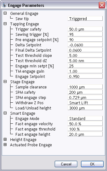
Figure 1: Default SPM parameters panel settings for indentation
|
|
|
To verify that the tip is off the surface, check that the Z piezo is retracted by looking at the image window—the Z center position should move to the retracted side of the indicator located on the Realtime status bar and the word “Limit” should appear in place of the Z center voltage value. If this does not occur, the Z piezo is not fully retracted and the tip may still be on the surface; decrease the Deflection setpoint by 1 V increments until Z is retracted. |
The tip velocity (μm/s or nm/s) is calculated by multiplying the Scan size (μm or nm) by twice the Scan rate (Hz).
Since the Lines parameter determines the number of scan lines made during the test, its value will effect the outcome of the wear test. NOTE: When performing wear tests on multiple samples, to compare properties, the following parameters should remain fixed for all tests:
|
|
|
|
As soon as the Deflection setpoint is increased by a sufficient amount, the tip will return to the surface and start to wear. Thus, it is important to execute the Frame Up/Down immediately, to begin a fresh scan. The force applied normal to the sample is set using the Deflection setpoint. In Contact Mode, the Deflection setpoint is a measure of the cantilever deflection when scanning the surface. The force also depends on the free-air vertical deflection, which should be set near zero prior to engaging. For further information on force calculations for wear testing, refer to Interpreting Hardness Data. |
|
|
|
|
|
Refer to Procedure for Nanoindenting for TappingMode engage guidelines using indentation cantilevers. Do not reset the X and Y offsets or the tip will engage in a different location. Once engaged, set the Scan size to a value greater than the value used for the wear test, and image the new features. |
If the application requires non-standard indentation cantilevers with lower spring constants than standard indentation cantilevers, imaging the worn area may require switching to a standard TappingMode or Contact Mode probe. If this is the case, it may be necessary to reference the location of the worn areas using a specific feature on the sample prior to performing the test. This is necessary as the tip position relative to the sample will not be the same after changing probes. If the worn area is visible through the optics used to view the sample a reference point is not necessary.
Switching to another probe may also be necessary if the indentation cantilever is not adequately imaging the worn area. This sometimes occurs when the wear procedure creates a large amount of debris in and around the worn area. The debris is sometimes pushed around or picked up by the stiff indentation cantilever, resulting in poor image quality.
Before switching to other imaging probes the user should attempt to image using the indentation cantilever in TappingMode. This is best accomplished by using the lowest imaging force possible. Use the maximum Amplitude setpoint possible while still tracking the surface. Also, increasing the Integral gain may improve the image quality by increasing the feedback response. It may help to scan the worn area in the same scan direction (up/down) in which the wear test was performed, since most of the debris is usually located at the end of the scan. This will prevent debris from ruining the entire scan because the tip will not contact the debris until the end of the scan.
| www.bruker.com | Bruker Corporation |
| www.brukerafmprobes.com | 112 Robin Hill Rd. |
| nanoscaleworld.bruker-axs.com/nanoscaleworld/ | Santa Barbara, CA 93117 |
| Customer Support: (800) 873-9750 | |
| Copyright 2010, 2011. All Rights Reserved. |