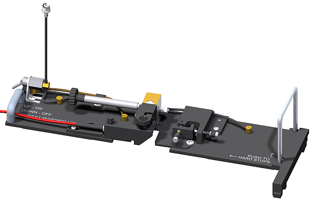
The Backside Illumination Optics Assembly, shown in Figure 1, conducts and focuses light from an external light source (typically from a solar simulator) on to the backside of the sample.
Figure 1: The Backside Illumination Optics Assembly
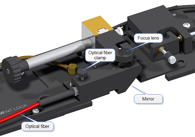
An optical fiber, shown in Figure 2, conducts the light through a condensing lens leading to a 45° mirror which is then focused onto the sample.
The position of the 200 μm diameter light spot is adjusted by the X-Y stage to keep it centered on the probe tip and focused on the sample by the Z stage, shown in Figure 3.
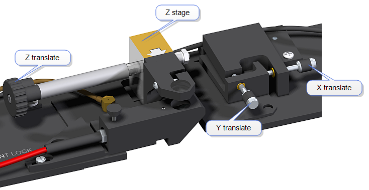
Figure 3: The Backside Illumination Optics Assembly stages
The Backside Illumination Optics Assembly is secured to the granite base of the Dimension Icon by vacuum that is sealed by a pair of O-rings, shown in Figure 4.
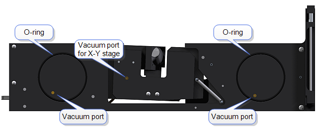
Figure 4: The bottom of the Backside Illumination Optics Assembly
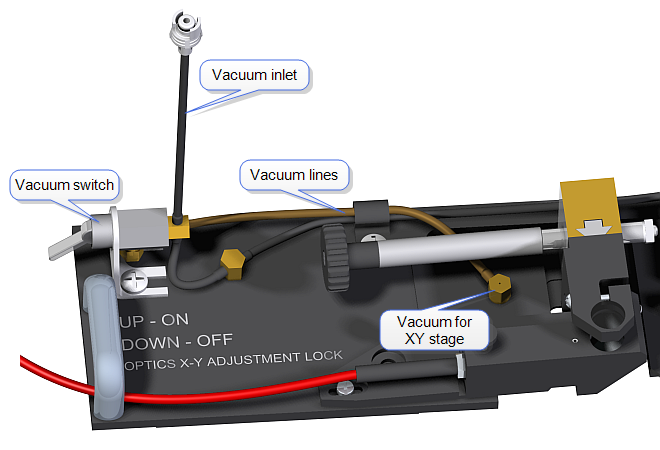
Vacuum is brought to the Backside Illumination Optics Assembly via the vacuum inlet, shown in Figure 5, and routed through a vacuum switch that controls the vacuum that is used to hold the X-Y stage in position.
| www.bruker.com | Bruker Corporation |
| www.brukerafmprobes.com | 112 Robin Hill Rd. |
| nanoscaleworld.bruker-axs.com/nanoscaleworld/ | Santa Barbara, CA 93117 |
| Customer Support: (800) 873-9750 | |
| Copyright 2010, 2011. All Rights Reserved. |