Removal Instructions
- Raise the head to the top of its travel.
- Move the chuck to the front left.
- Remove the head.
- Remove the clamps. probe and sample. Put the clamps and probe in the storage case.
- Remove the terminal block and put it in the storage case.
- Remove the two M3 cap screws [2.5 mm hex drive] that hold the chuck and put them in the storage case. See Figure 1.

Figure 1: Remove the two M3 x 8 mm socket head cap screws
- Remove the chuck.
- Disconnect the vacuum line from the microscope.
- Remove the Backside Illumination Optics Assembly.
- Move the Backside Illumination Optics Assembly X-Y stages to align the holes and insert the white plastic screws. Place the Backside Illumination Optics Assembly in the storage case.
- Reinstall the alignment station. Push the alignment station to be flush with the stop. See Figure 2.
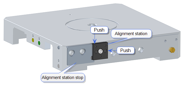
Figure 2: Install the alignment station
- Check the taught position of the alignment station and re-teach if necessary.
| www.bruker.com
|
Bruker Corporation |
| www.brukerafmprobes.com
|
112 Robin Hill Rd. |
| nanoscaleworld.bruker-axs.com/nanoscaleworld/
|
Santa Barbara, CA 93117 |
| |
|
| |
Customer Support: (800) 873-9750 |
| |
Copyright 2010, 2011. All Rights Reserved. |
Open topic with navigation