
The following steps show how to get Vertical and Horizontal Piezoresponse data using the Generic Lock-Ins. This procedure is not necessary for PFM Optimized Vertical Domains Operation.
The example experiment below was performed on a PZT thin film. While the PPLN sample may show lateral contrast, the interpretation of the contrast is difficult. To map the lateral domains simultaneously with the vertical domains, the Generic Lock-In feature using two lock-ins simultaneously will be used. Orient the sample so that the domains are parallel or perpendicular to the tip scan direction.
|
Channel Number |
Channel Data Type |
Real-Time Plane Fit |
Off-Line Plane Fit |
|
1 |
Height (retrace) |
Line |
Full |
|
2 |
Deflection error (retrace) |
Line |
Full |
|
3 |
Amplitude 1 (retrace) |
None |
None |
|
4 |
Phase 1 (retrace) |
None |
None |
|
5 |
Amplitude 2 (retrace) |
None |
None |
|
6 |
Phase 2 (retrace) |
None |
None |
Below, the Amplitude1 and Phase1 channels show the vertical domains in the PZT film. The Amplitude2 and Phase2 channels show the lateral domains in the film.

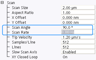
Sometimes, scanning the surface at a 45 degree scan angle may reveal more details than scanning at either 90 or zero degrees. The image below shows a 45 degree scan angle of the same PZT filmfrom above.

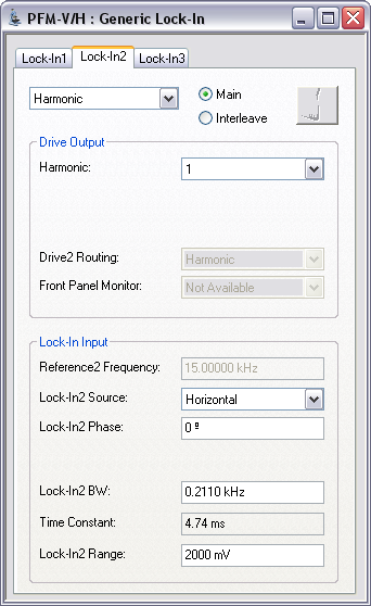
The Generic Lock-In can also be used to map the surface using higher harmonics. See Working With Higher Harmonics Using Generic Lock-Ins for details.
| www.bruker.com | Bruker Corporation |
| www.brukerafmprobes.com | 112 Robin Hill Rd. |
| nanoscaleworld.bruker-axs.com/nanoscaleworld/ | Santa Barbara, CA 93117 |
| Customer Support: (800) 873-9750 | |
| Copyright 2010, 2011. All Rights Reserved. |