![]() |
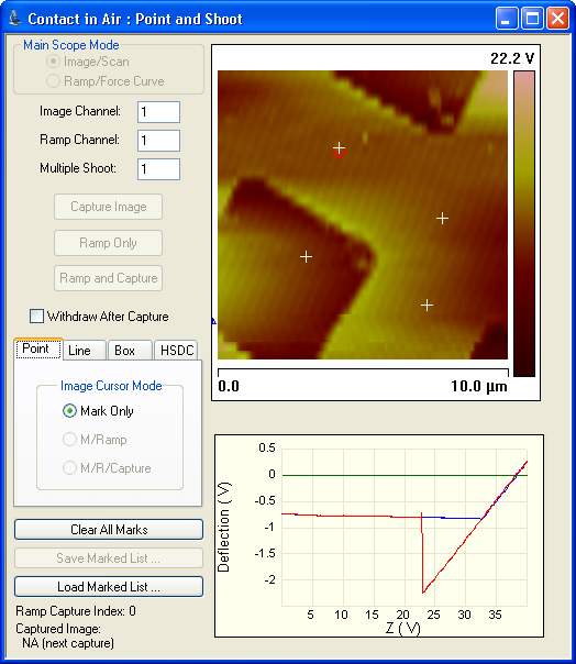
The Point and Shoot View allows you to select specific points on an image (see Figure 1). |
Use Point and Shoot to capture an image and/or collect a force curve for every point you designate. When you click a point on an image, a crosshair (+) marks the location. You can designate individual points, or use the tools in the Point and Shoot View to assign multiple points simultaneously. |
Figure 1: Point and Shoot View
Control | Description |
---|---|
Image/Scan |
Allows you to switch to Image/Scan mode. Use Image/Scan mode to adjust scan parameters in any scan view. |
Ramp/Force Curv |
Allows you to switch to Ramp/Force Curve mode. Use Ramp/Force Curve mode to adjust the ramp settings. You can select points on an image, ramp each point, and create a force curve for each point. |
Image Channel |
Select the channel to use for the image. |
Ramp Channel |
Select the channel to use for the ramp display. |
Multiple Shoot |
Number of force curves collected at each point, 100 max. |
Capture Image |
Click this button to capture an image and save it in the Capture Directory. After the capture the software switches to Ramp/Force Curve mode. |
Ramp Only |
Click this button to ramp a variable determined from the force curve menu at each point. |
Ramp and Capture |
Click this button to ramp each point, capture the ramp/force curve, and save it in the Capture Directory. |
Point Parameters |
Image Cursor Mode Settings: Mark Only—Select points of interest on the image. M/Ramp—Select points of interest. Software will automatically ramp each point. M/R/Capture—Select points of interest. Software will automatically ramp each point and capture a ramp/force curve. |
Line Parameters |
Draw a line to select specific points on an image. Point Number—Number of points in the line. Spacing—The distance in nm between each point. All points are equidistant. Clear Path—This button clears the current line and associated points. Convert to Points—Places a + in the location of each point in the line. The line disappears. |
Box Parameters |
Draw a box in the area you want to place a group of points. You can use the parameters below to create a grid of points. Row Number—Designates the number of rows of points in the grid. Column Number—Designates the number of columns of points in the grid. Row Space (nm)—Designates the distance in nm between each row of the box. Col Space (nm)—Designates the distance in nm between each column of the box. Clear Path—This button clears the current box and associated points. Convert to Points—Places a + in the location of each point in the grid. The box disappears. |
HSDC Parameters | Refer to thePoint And Shoot section in High Speed Data Capture |
Clear All Marks |
Removes all user-defined marks from the Point and Shoot image. |
Save Marked List.. |
Save the marks on the image as Path Files (*.psm). |
Load Marked List... |
Opens and loads a previously saved Path File (*.psm) which contains marks on a Point and Shoot image. Note: If there are points on the image prior to selecting this option, when this button is selected the saved marks will appear in addition to the previous marks. |
Two options are available for moving, in XY, from one point to another:
|
Figure 2: Ramp Parameters (Advanced Mode) > Mode > XY move on surface
www.bruker.com | Bruker Corporation |
www.brukerafmprobes.com | 112 Robin Hill Rd. |
nanoscaleworld.bruker-axs.com/nanoscaleworld/ | Santa Barbara, CA 93117 |
Customer Support: (800) 873-9750 | |
Copyright 2010, 2011. All Rights Reserved. |