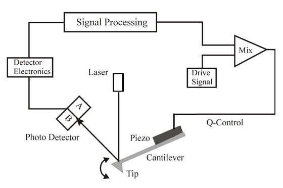
The following is a mathematical model for control of the Q of a resonating cantilever by feedback of its detected oscillation.
Figure 1: Q Control Block Diagram
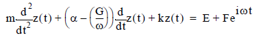
The equation of motion of the tip of a driven cantilever with feedback is given by a balance of forces [1]:
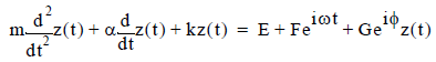
expressed in terms of the unknown, variable over time, t: position of the tip, z(t), as well as tip velocity,  , and acceleration,
  , first and second derivatives of position, respectively, and
Assuming a solution where the cantilever begins at position z(0) = 0, oscillates at the drive frequency, and has no components at higher frequencies, then
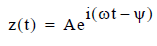
and
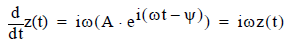
where
The sinusoidal probe tip motion is described as a phasor in exponential form: a counterclockwise rotating line segment in the complex number plane (i.e., a real number horizontal axis and an imaginary number vertical axis) such that the segment length corresponds to the oscillation amplitude, its rotation rate corresponds to the oscillation frequency and its angle corresponds to the phase of the oscillation.
Consider the case of a 90 degree phase shift applied in the feedback loop, that is: φ = π/2. The third term on the right-hand side of the equation of motion becomes:

which can be subtracted from both sides of the equation of motion to yield:
A new cantilever equation of motion results. In the new equation of motion, there is no feedback term while the tip/sample interaction and drive forces are the same as in the original equation of motion. Significantly, the original damping constant, a, is replaced by a new one, α' = α – (G/ω).
Given that the width of the resonance at half-maximum, γ, equals the damping constant, α', divided by the effective mass of the system, m, the Q of the resonance is given by:
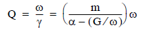
The result shows that any solution of the chosen form also solves a feedback-free equation of motion with a different damping constant. For a properly chosen Q control feedback phase shift (i.e., φ = π/2), the Q control feedback amplifier gain, G, determines the damping, and therefore the Q of the cantilever oscillation.
Reference
[1] Piconewton Regime Dynamic Force Microscopy in Liquid, Javier Tamayo, Andrew D. L. Humphris, Mervyn J. Miles, Applied Physics Letters, Vol. 77, No. 4, p. 582, July 24, 2000
| www.bruker.com | Bruker Corporation |
| www.brukerafmprobes.com | 112 Robin Hill Rd. |
| nanoscaleworld.bruker-axs.com/nanoscaleworld/ | Santa Barbara, CA 93117 |
| Customer Support: (800) 873-9750 | |
| Copyright 2010, 2011. All Rights Reserved. |