The Cantilever Tune command allows determination of the cantilever resonant frequency and the setting of the operating point for TappingMode feedback (see Figure 3.1t). Cantilever Tune sweeps the cantilever drive frequency over a selectable range, then displays plots of the cantilever amplitude and phase versus drive frequency. This command is enabled only when the Microscope mode parameter in the Other panel of the Scan Parameter List is set to Tapping. On Small Sample MultiMode SPMs, verify that the switch located on the base is toggled to TM AFM before selecting the Cantilever Tune command.
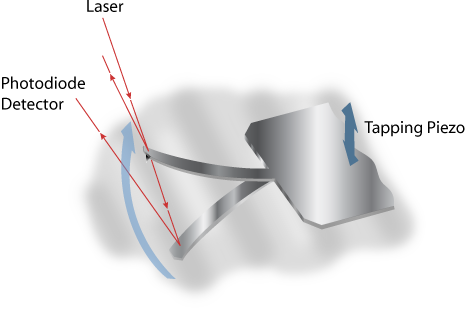
Figure 1 shows how the maximum amplitude is attained in air at the cantilever natural resonance. Figure 2 shows the amplitude is reduced when it is in contact with the sample surface.
Figure 1: Tapping cantilever in mid-air
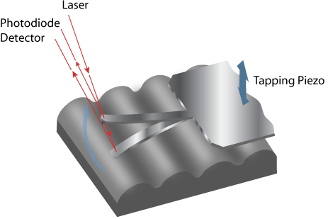
Figure 2: Tapping cantilever on sample surface
|
In TappingMode, the optical lever technique reflects a laser beam off the back of the oscillating cantilever, thence to a segmented photodiode. The differential signal between the top and bottom photodiode segments provides a sensitive measure of cantilever deflection. As the sample is scanned, analog circuitry determines the RMS value of the rapidly changing cantilever deflection signal. The RMS value of the cantilever deflection signal corresponds to the amplitude of the cantilever oscillation. Changes in amplitude of the cantilever oscillation are controlled by the feedback system to track the sample surface. |
|
|
|
Access the Cantilever Tune dialogue box, shown in Figure 3, by selecting the Tune icon or by selecting Cantilever Tune from the Microscope menu. |
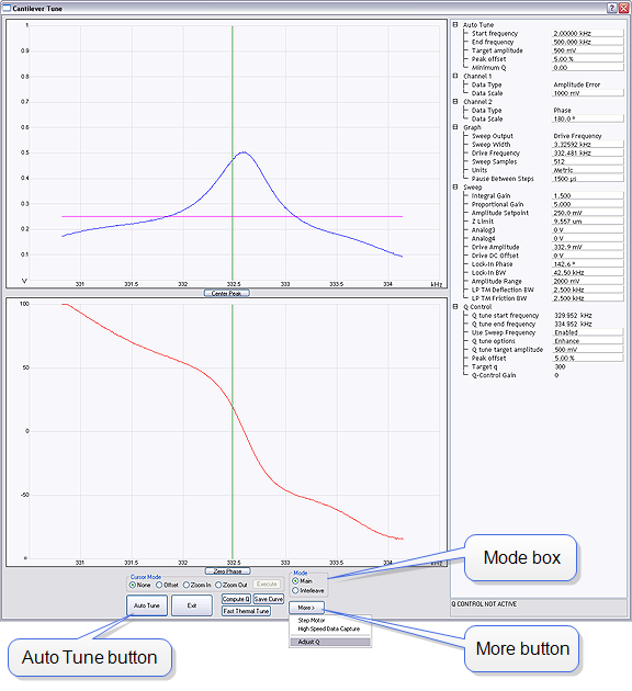
Figure 3: The Cantilever Tune dialog box
| Definition | |
|---|---|
|
Mode box |
Toggles the Auto Tune signal from the main to interleave signals. Settings: Main— Displays the set of parameters applied to the main scan (see Scan Window). Interleave—Displays a duplicate set of parameters applied only to the interleaved portions of the scan. |
| Auto Tune Button | Executes the automatic tuning procedure: the cantilever is excited through a range of frequencies beginning at the Start frequency and ending at the End frequency. |
| Parameter | Definition |
|---|---|
|
Start frequency |
Starting point of the Auto Tune frequency sweep. |
|
End frequency |
Ending point of the Auto Tune frequency sweep. |
|
Target amplitude |
Targeted output signal amplitude at the photodiode detector. This value should not be confused with Drive amplitude, which is the amplitude applied directly to the cantilever itself (see Drive amplitude). Range and Settings: 0.00 to 8.00 V Note: Dimension Series SPMs, nominal = 500mV .Small Sample MultiMode SPMs, nominal = 500mV |
|
Peak offset |
Percentage of cantilever’s free-air resonant frequency to be automatically offset. Peak offset is used to compensate for changes in resonance before engagement due to the tip’s interaction with the surface after engagement. Range and Settings: 0 to 50%; typical value = 5% |
|
Minimum Q |
Q is the value defined by the amount of oscillation it takes for a wave to drop to 1/e (e = 2.718) of its amplitude value (i.e. a wave with an amplitude of ten would have a Q of 10/e, or 3.6788). Minimum Q establishes a minimum “width of peak” value allowed by the AutoTune function. Peaks not meeting the Minimum Q may be ignored by setting the Smash width factor. |
|
Smash width factor |
The width of the area beneath the wave smashed (set to zero) when a peak not meeting the Minimum Q requirement is found. Note: This parameter does not appear if Minimum Q is 0. |
| www.bruker.com | Bruker Corporation |
| www.brukerafmprobes.com | 112 Robin Hill Rd. |
| nanoscaleworld.bruker-axs.com/nanoscaleworld/ | Santa Barbara, CA 93117 |
| Customer Support: (800) 873-9750 | |
| Copyright 2010, 2011. All Rights Reserved. |