Eurovac deposition system
Responsible:
Taras
Golod,
Procedure when using SiO2 sputter target!
2011-03-16, Stefan Rosén, A. Liljeborg
The sputtering of SiO2 is causing subsequent sputtering of
gold to generate flakes falling of the surfaces. The gold will not
stick to surfaces covered with SiO2. To remedy this a
sticking layer of titanium must be deposited after each
SiO2 sputtering.
-
Always sign in the Logbook.
-
Gold does not stick on the SiO2.
-
Before Gold deposition check the logbook and if necessary start with
about 5 nm Ti deposition.
End of procedure when using SiO2 sputter target.
Service information
Short description how to use sputter guns
Manual for thickness monitor (pdf)
| New tool factor =
| old tool factor × measured film thickness
|
|
| desired film thickness
|
Modifications, 2015-06-05, T. Golod
- New vacuum gauge is installed which has a measurement range
from 5 × 10⁻⁴ to 1500 mbar. It sits on top of the
load-lock and has
built-in small display.
- The valve between turbo pump and load-lock is removed. The pump
is now mounted to the back side of the load-lock so there is no risk
of dropping your sample into the turbo when mounting or unmounting
the sample holder.
- The backing pump is moved to the service corridor so there is
less noise when turbo is ON.
- The nitrogen vent valves are removed so the venting of the
load-lock is done through the turbo pump vent valve. There is no
risk of killing the pump by venting the load-lock when turbo is ON.
According to this there are some changes to the loading and unloading
procedure, see below.
Short user guide
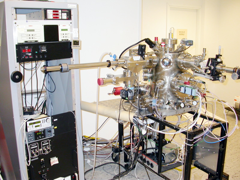
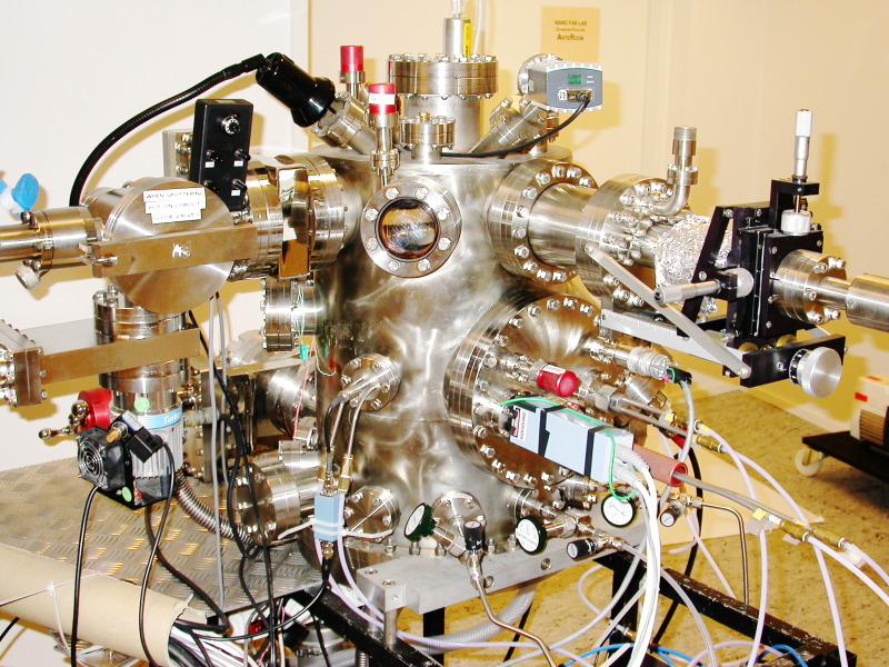
Overview image of the system
Loading Sample:
- Put samples on the sample holder and make sure they are secure.
- Make sure that the valve into main chamber is closed.
- Vent the load-lock by switching off the load-lock turbo pump.
- Wait for atmospheric pressure.
- Attach the sample holder to the transfer rod (using fresh gloves),
check that all 3 clamps are ok.
- Close load-lock.
- Pump down by switching on the load-lock turbo pump while gently
holding load-lock tight.
- When turbo controller says "normal operation" the pump down is
finished (check the pressure in load-lock. Should be below
5×10⁻⁴ mbar).
- Open the valve into main chamber.
- Transfer sample from rod to internal holder (make sure internal
holder is at 270 degree).
- Remove the transfer rod.
- Close main chamber valve.
Depositing
There are silver colored labels with numbers from 1-6,
placed on the various handles, levers, etc. on the system.
These labels are indicated in brackets in the following description.
Select what metal to deposit, selected by turning
long red handle with holes
at the front. There is a list of which metals are at
which positions on the wall. There are 12 turns between adjacent
positions for each metal.
-
Crucible no. 1 is selected when the end of the
thread is visible in the hole closest to the chamber.
- Crucible no. 5 is selected when the end of the thread is even
with the end of the red handle.
- Check logbook: if SiO2 has been sputtered always
start deposit 5 nm Ti.
- Make sure that correct material (crucible) and deposition program are selected
- Turn the sample to 0°.
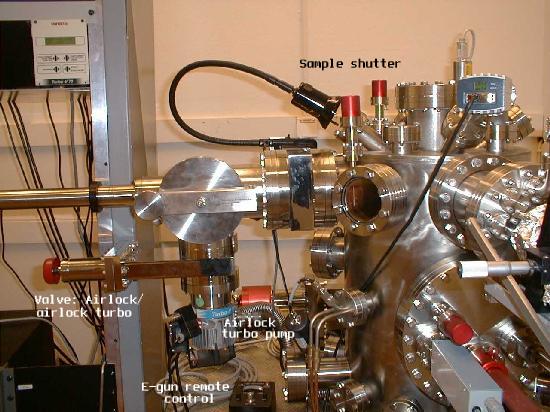
- Close sample shutter
- Open Target shutter [4]
- Turn on main e-gun power supply (check that cooling water is on) [1]
- Turn on sweep control [2]
- Turn on gun current [3]
- Slowly increase the filament current (steps of 0.10 with 20 sec wait in between) [5]
- After reaching 1.0 start increase continuously (but still slowly) until you get a stable rate.
- Open sample shutter and at the same time press "zero" on
the thickness monitor [6]
- Close window shutter to avoid depositing material on view port
- Change angle if desired
- When desired thickness is achieved, close the Sample shutter
- Turn down current
- Turn off gun current
- Turn off sweep control
- Turn off main e-gun power supply (keep the cooling water on)
Unloading
- Open window shutter.
- Close target shutter.
- Open sample shutter.
- Rotate sample holder to 270 degree.
- Check that the vacuum in the load-lock is below
5×10⁻⁴ mbar.
- Open main chamber valve.
- Insert transfer rod.
- Remove sample holder.
- Close main chamber valve.
- Vent the load-lock by switching off the load-lock turbo pump.
- Wait for atmospheric pressure.
- When load lock opens, take out sample holder (Using fresh gloves).
- Close load-lock.
- Switch on the load-lock turbo pump.
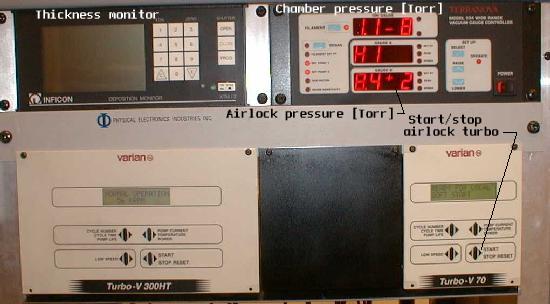
Upper part of electronics rack showing:
| Thickness monitor
|
Pressure meter for airlock and chamber
|
Turbo pump control for main chamber
|
Turbo pump control for airlock
| |
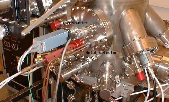
Main chamber with metal selector.
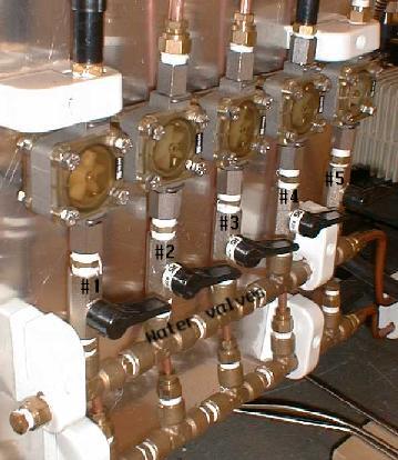
Cooling water valves.
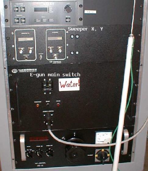
Lower part of rack, showing sweeper and e--gun mains switch.
Close-up view showing the different valves and shutters
View from different angle of central parts of the deposition system.
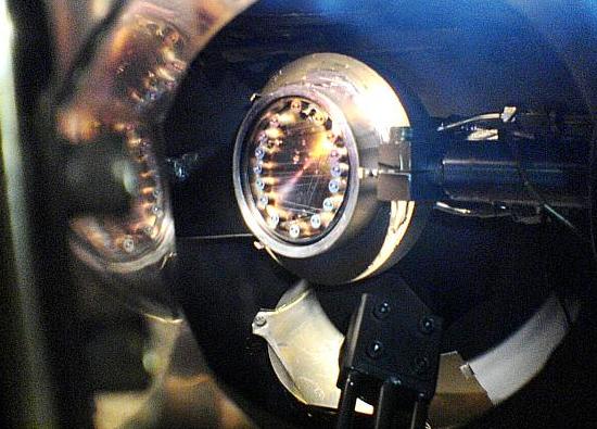
Through viewport, empty sample holder.
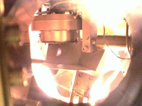
Through viewport, sample rotated downwards, sputtering active.
Service information
How to vent the main chamber, added 2019-07-10
- Check that load lock is pumped down
- Open load lock valve
- Shut valve in front of turbo
- Leave turbo on
- Vent load lock (and thereby the main chamber)
- Wait 10-20 minutes, until load lock door opens
- Open blank flanges, perform service.
- Close load lock door
- Pump load lock (and chamber)
- Wait until 10-4 mBar
- Open valve in front of turbo
- Close load lock valve
- Pressure should go down to 10-8 in one - two days.
Cesar
600 W RF power generator manual (pdf) for sputtering target. Limited access.
Cesar
auto-matching unit manual (pdf) for sputtering target. Limited access.
Short description how to use sputter guns
Service, cleaning, 2005-10-14
E-gun, melted leads to filament, 2004-05-28
E-gun, arcing, 2004-02-11
Movie of loading (MPEG4, .mp4)
Courtesy
of Daniel Öijerholm-Ström, taken with cell-phone camera.
Anders Liljeborg
NanoLab, KTH.